Click on any image to open it in a new tab and zoom in for a closer look.
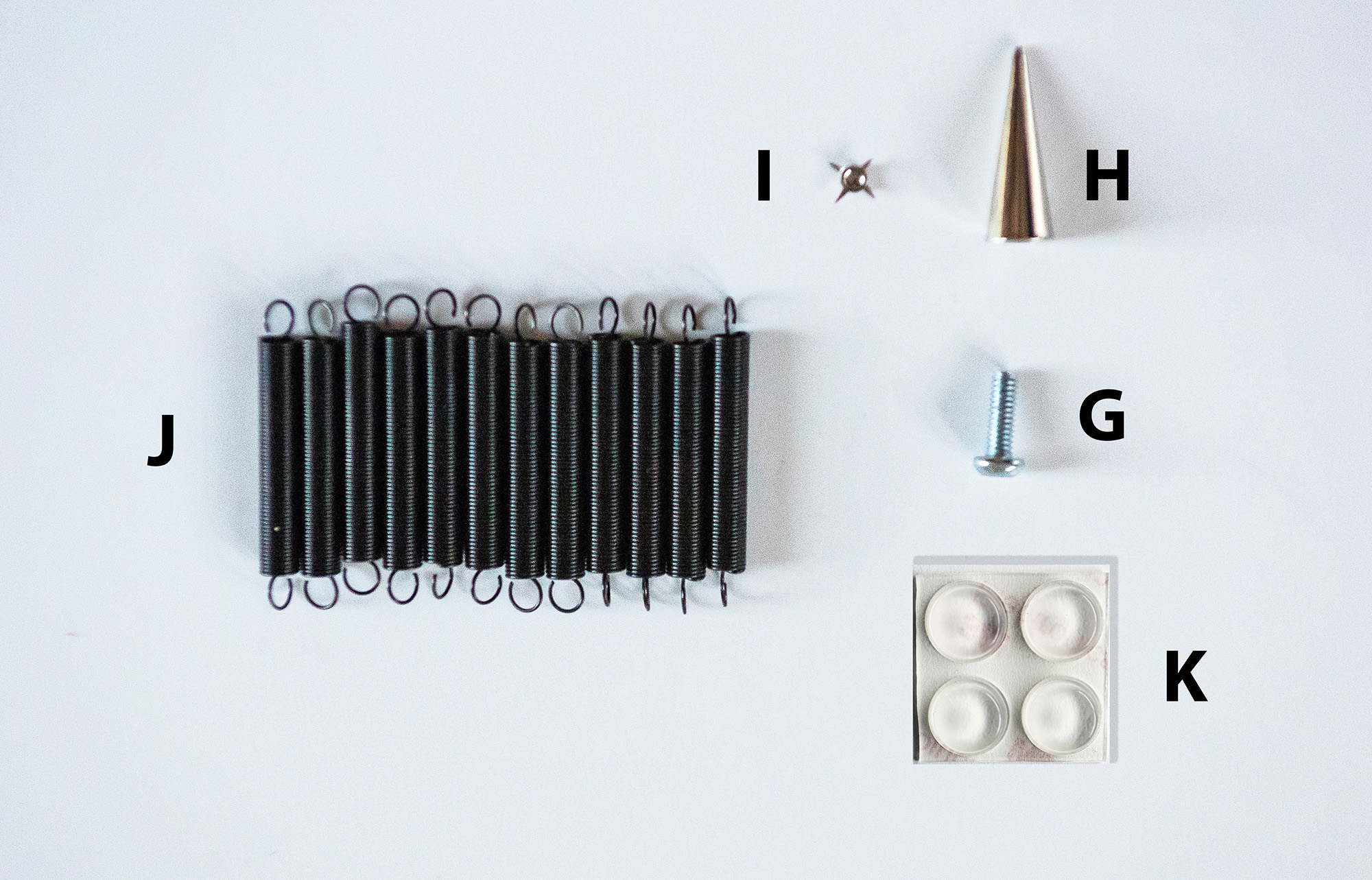
The HovErgo Hardware kit contains the non-3D-printed parts from the HovErgo Mouse Pad. It includes:
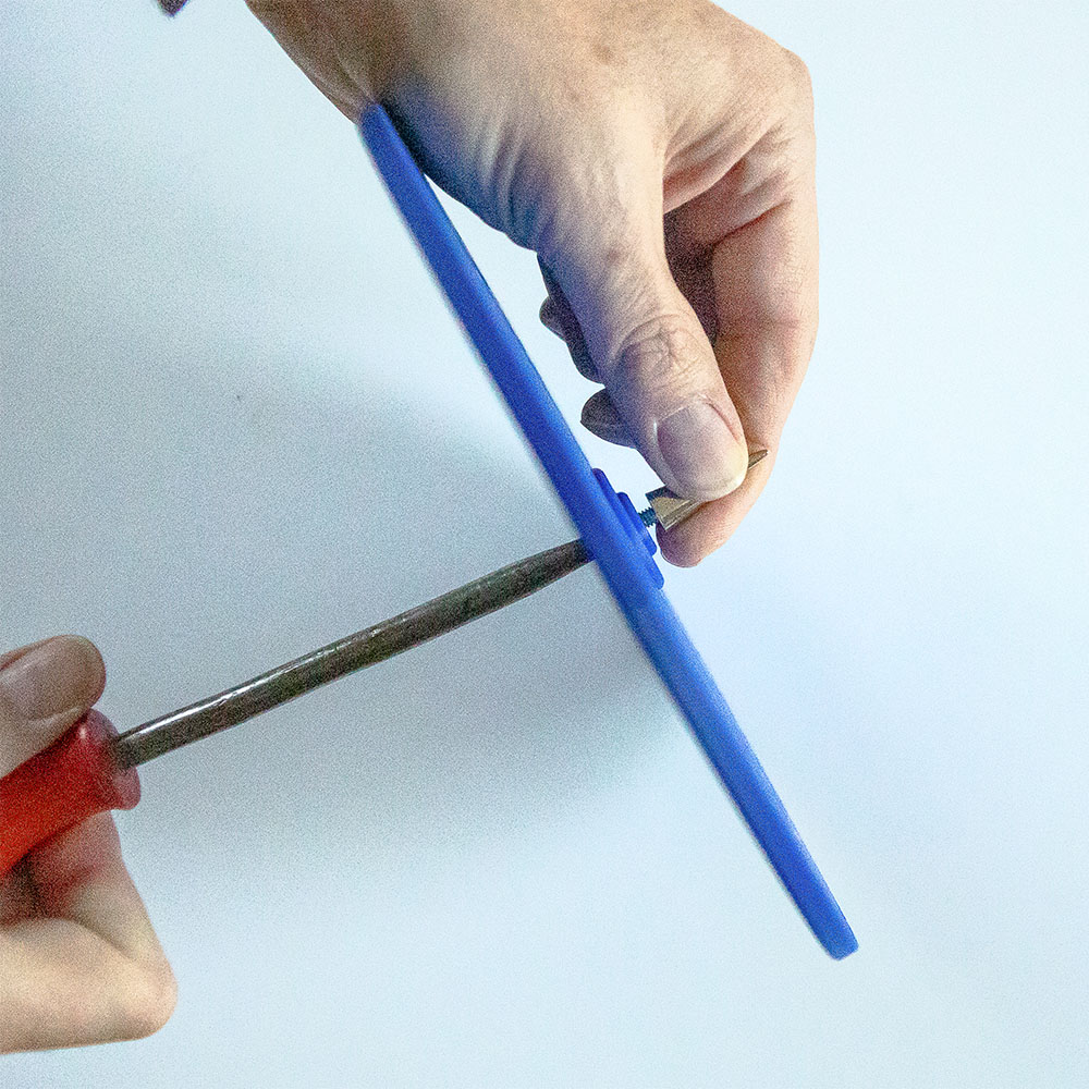
- G. Screw to secure the spike to the bottom platform.
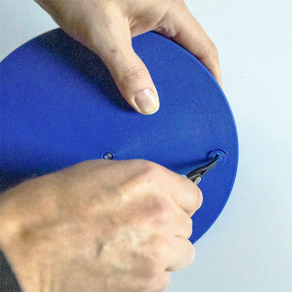
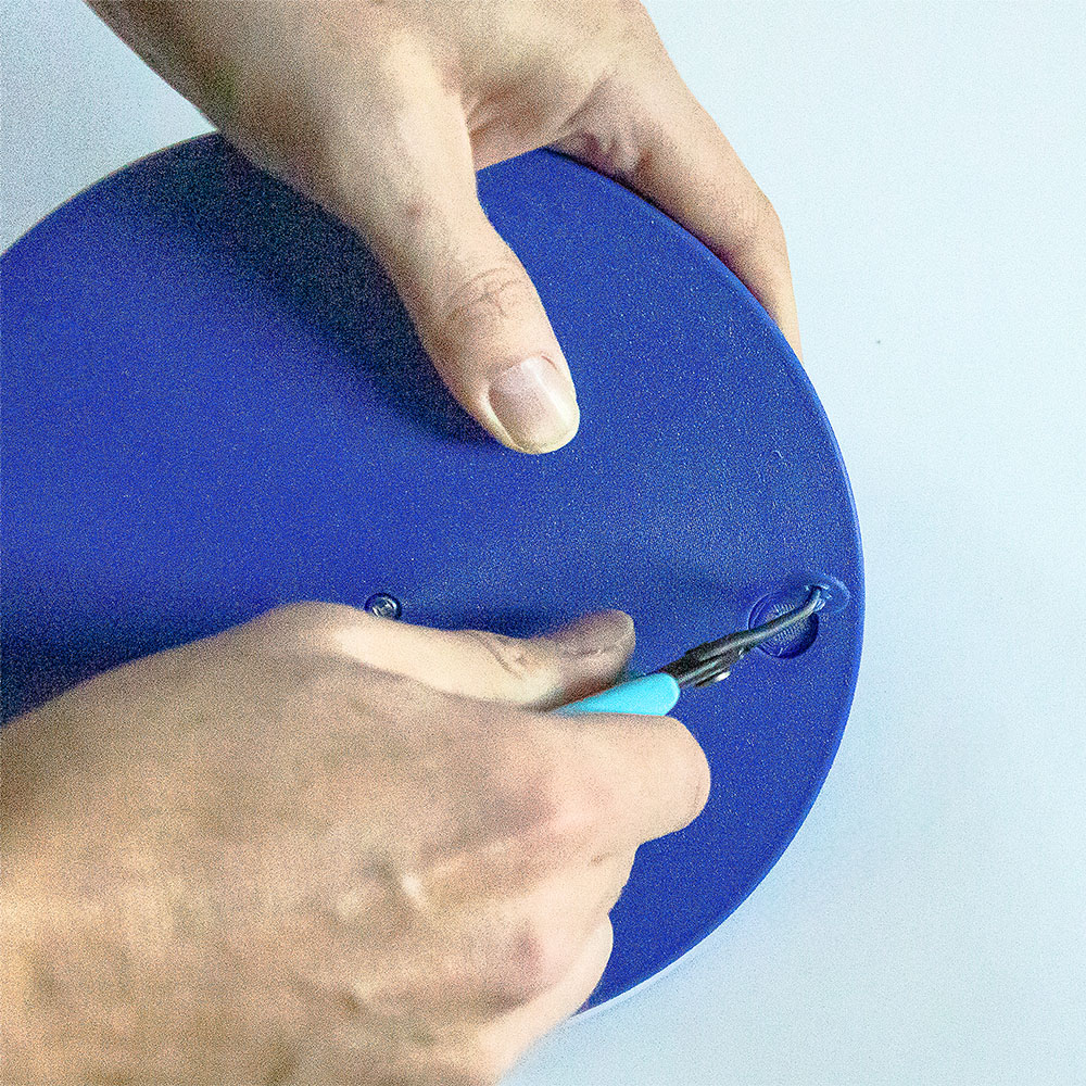
- H. Metal spike that provides center balance for the tilting mechanism.
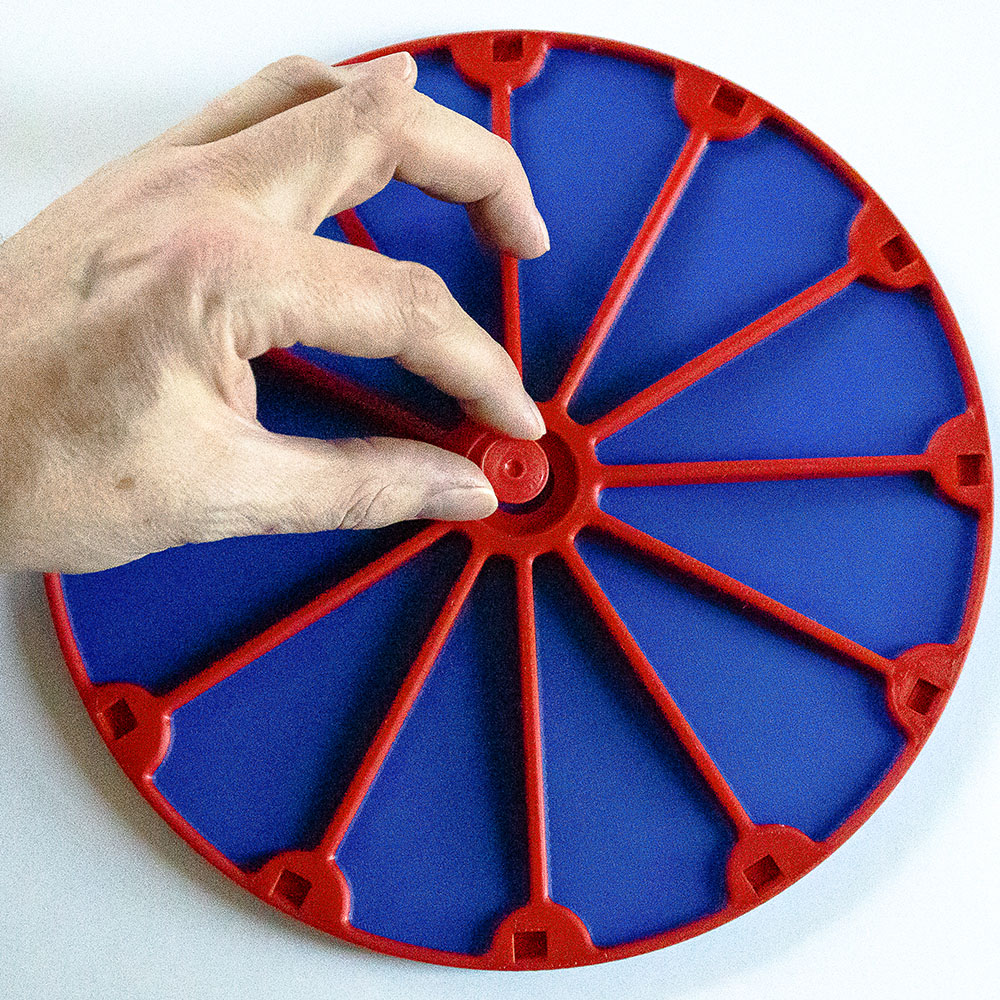
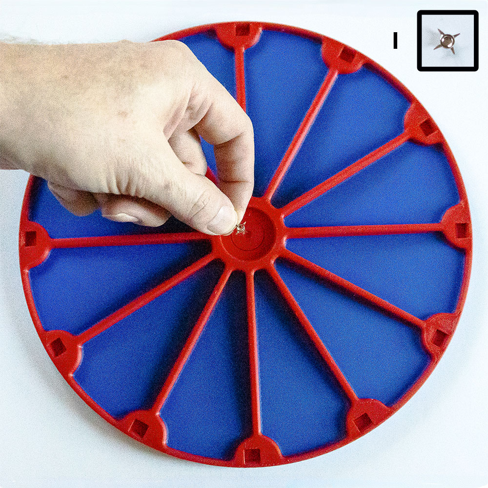
- I. Balance cap to protect the top platform from wear caused by the spike.
- J. 12 springs to manage the tilting motion of the platform.
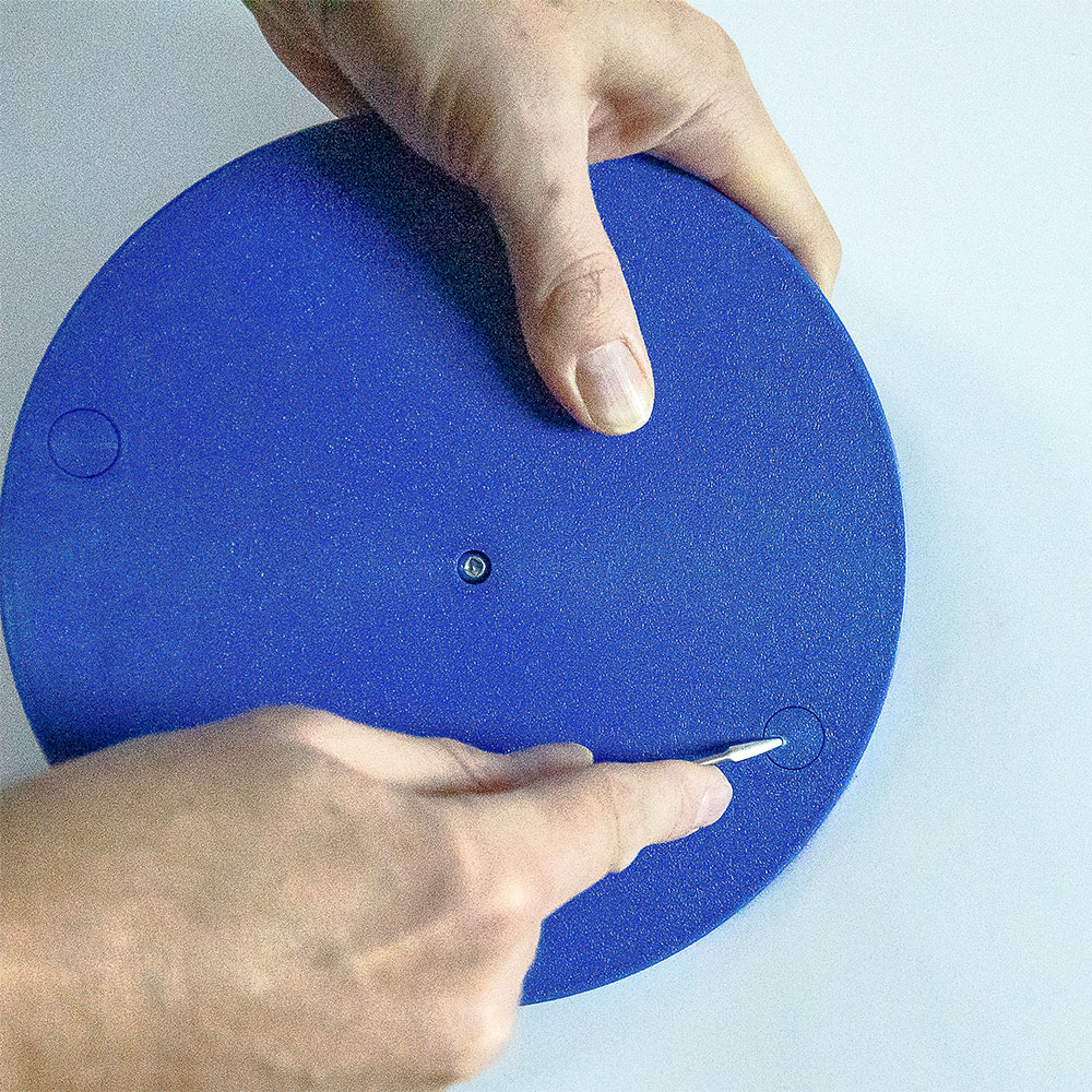
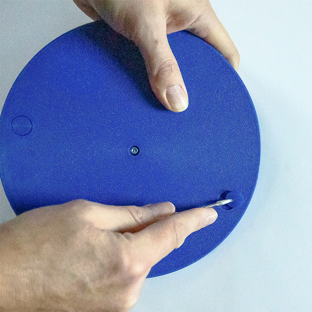
- K. Clear silicone anti-slip pads for added stability.
Displayed below is the hardware kit along with all 3D-printed parts:

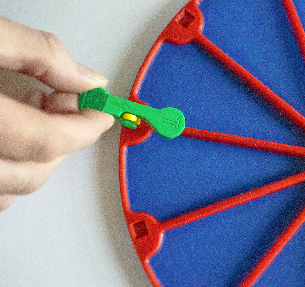
- A. Slot Key to screw in Balance Cap Retainer
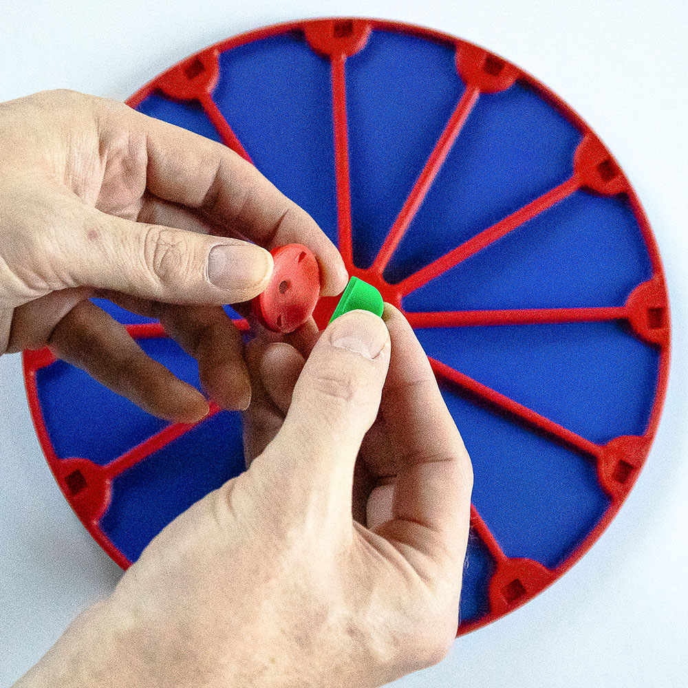
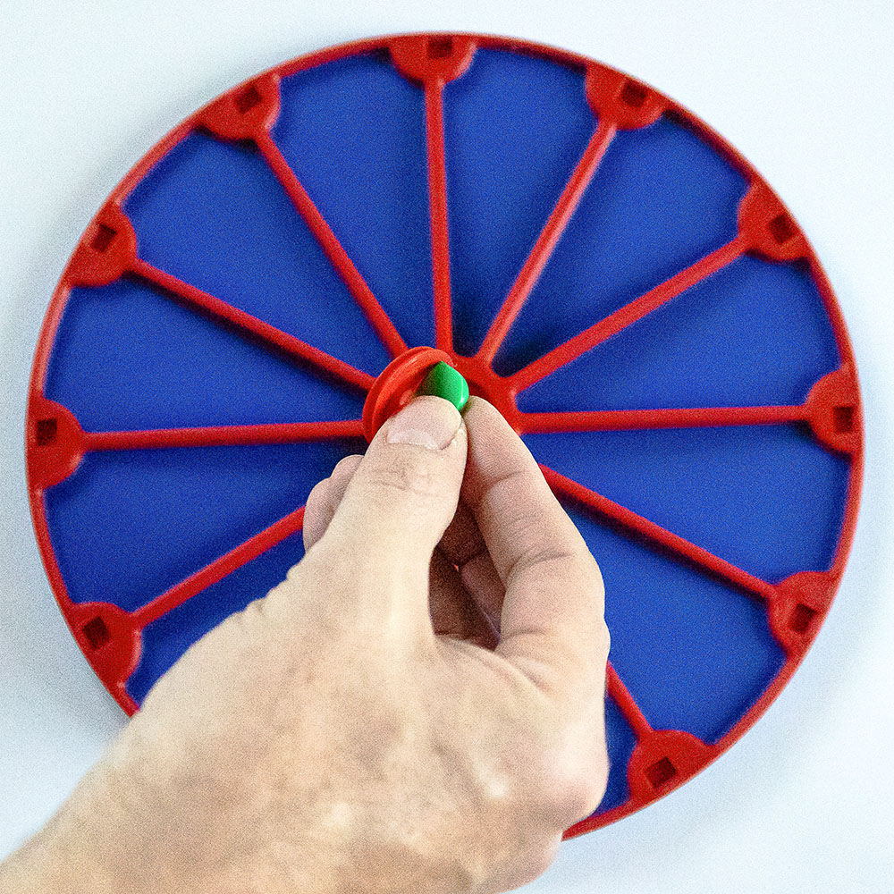
- B. Balance Cap Mount with socket to fit the Balance Cap
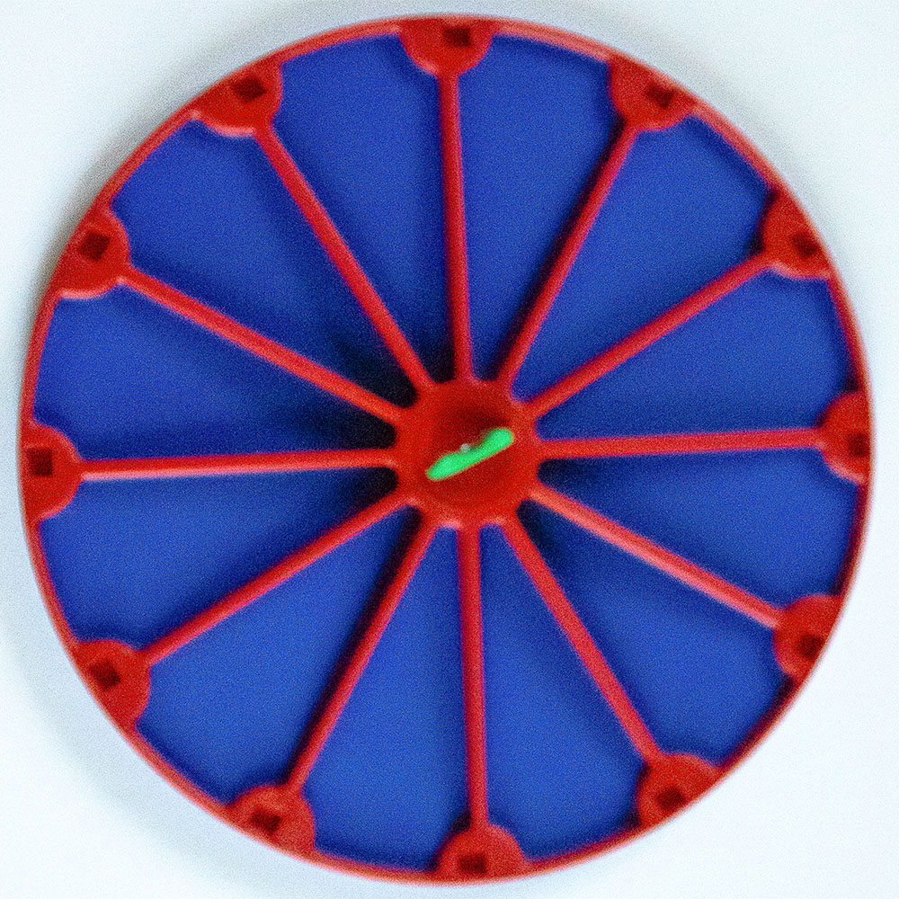
- C. Balance Cap Retainer to secure the Balance Cap onto the Top Platform
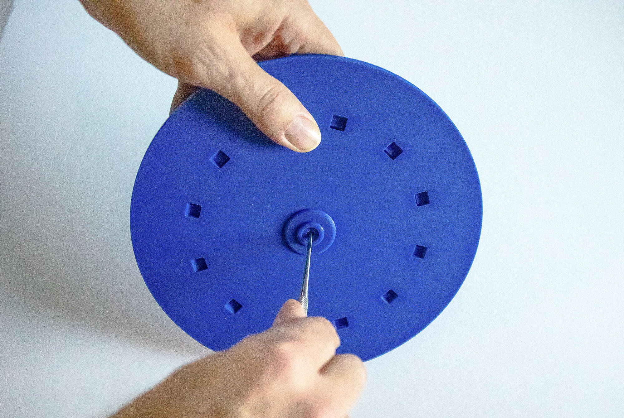
- D. 12 Top Platform Hooks for the springs
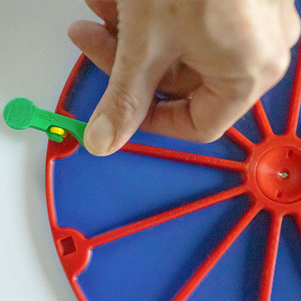
- E. Top Platform Hook Insert Tool
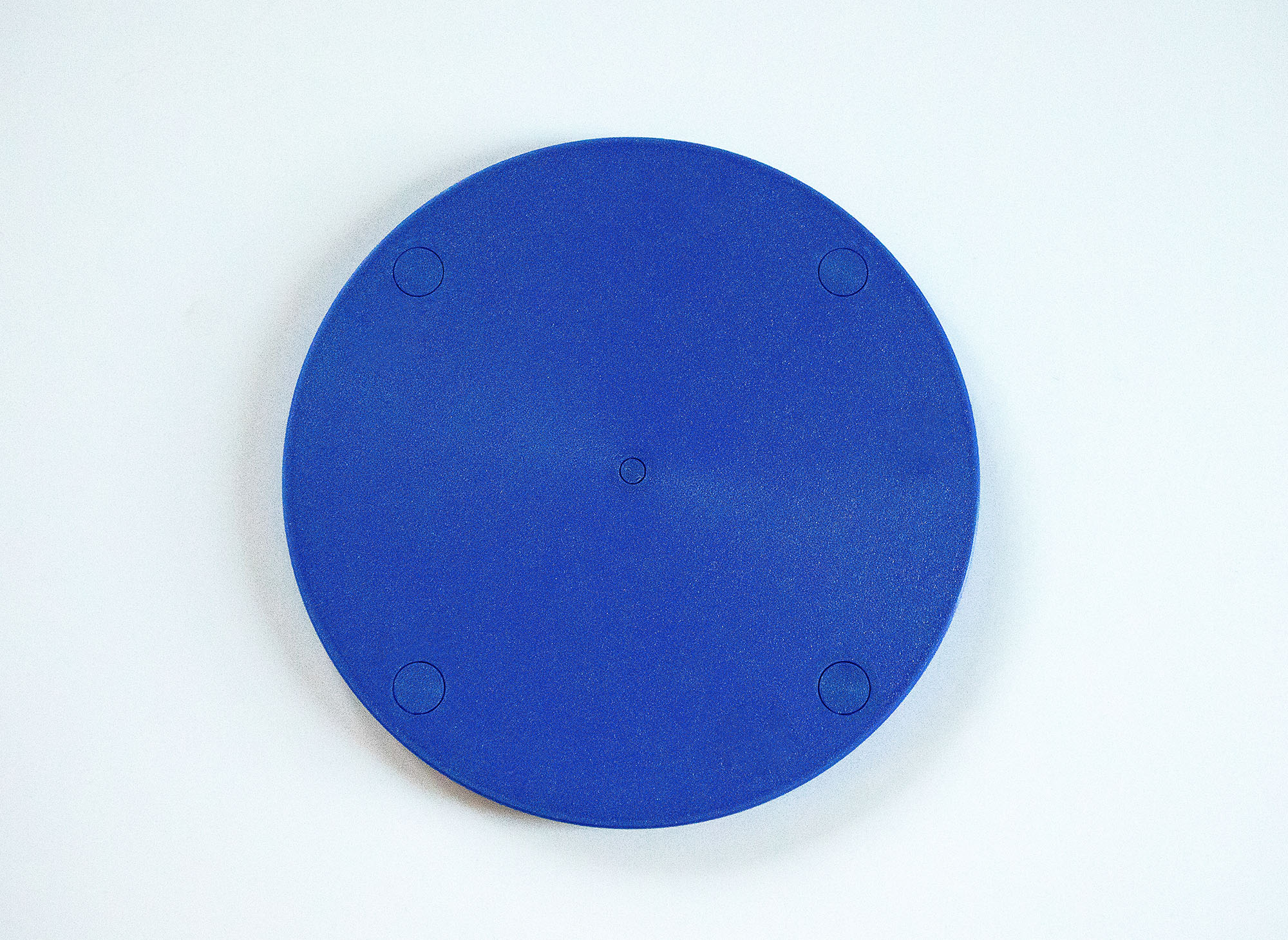
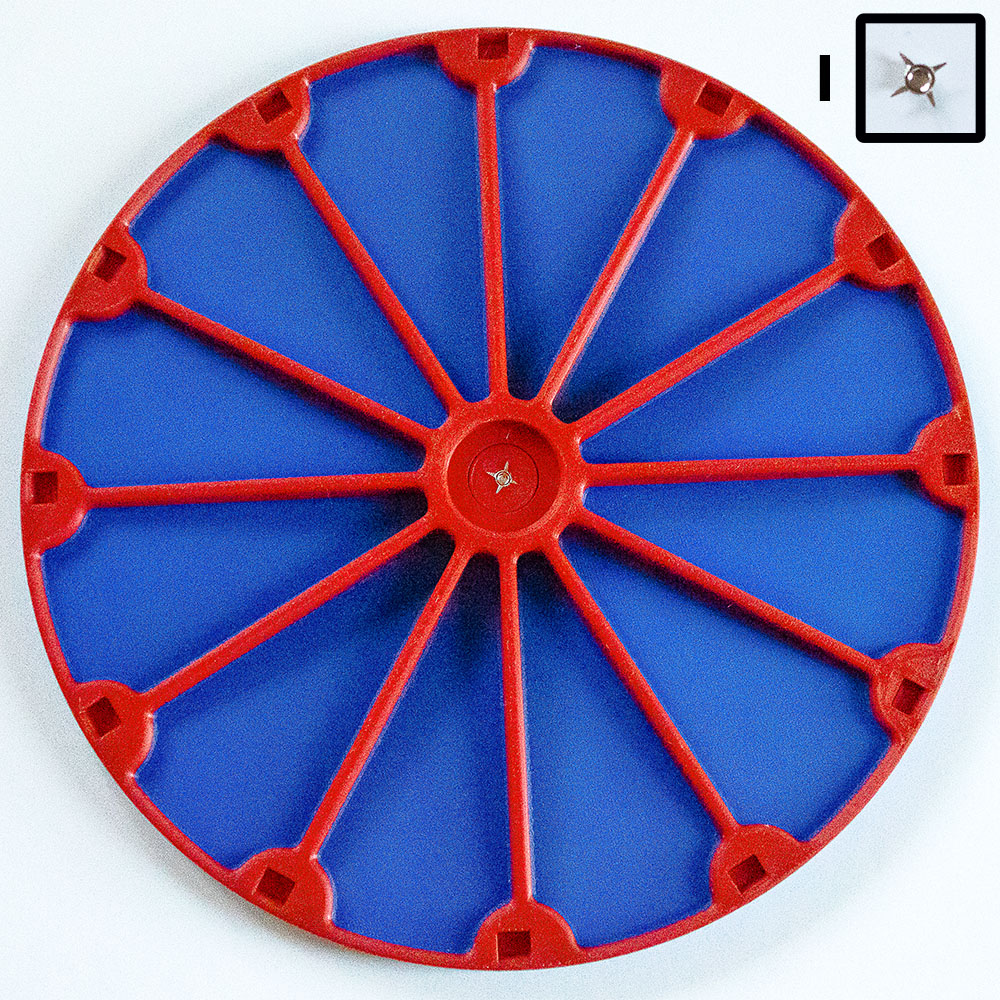
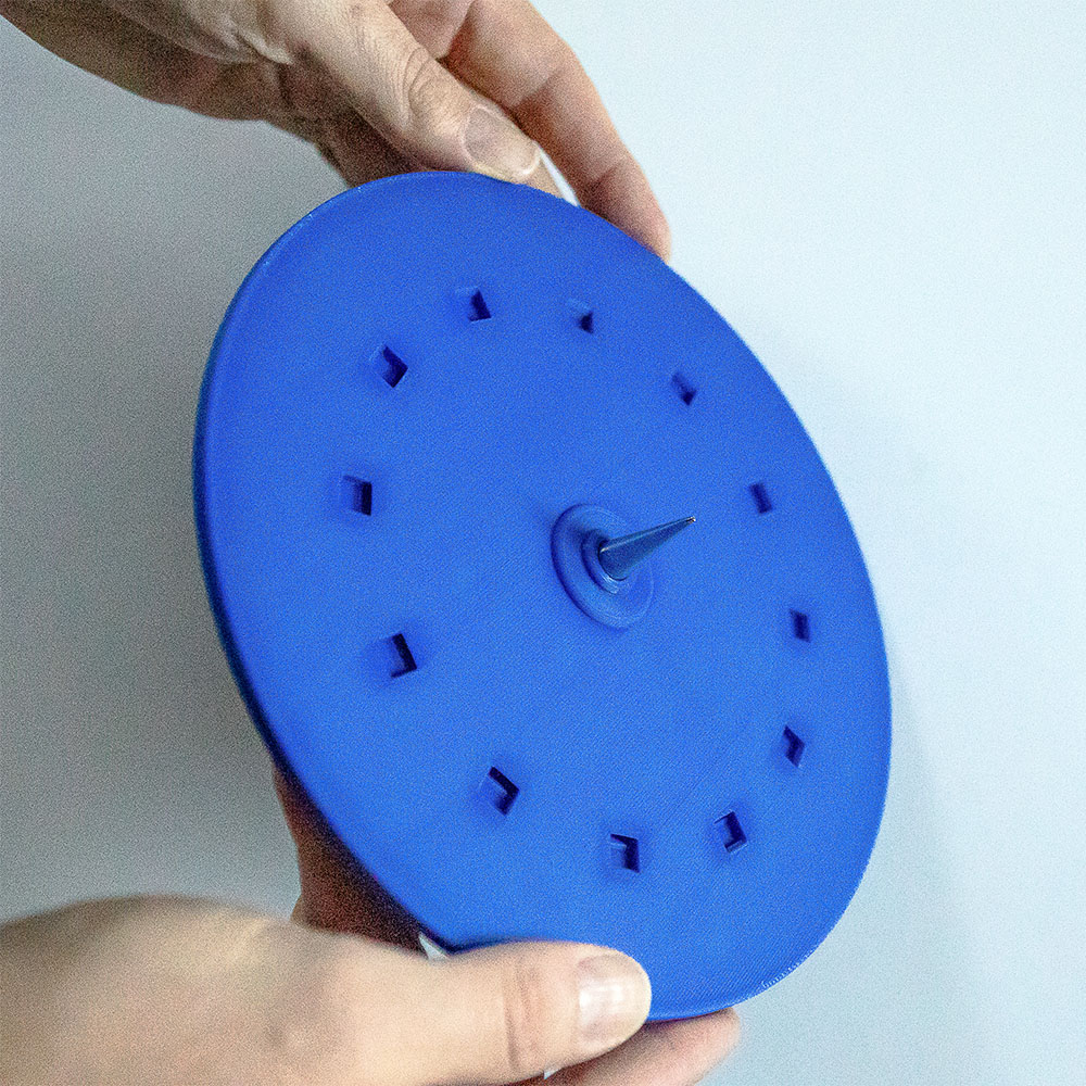
- F. Top Platform
- G. Screw for Spike
- H. Spike
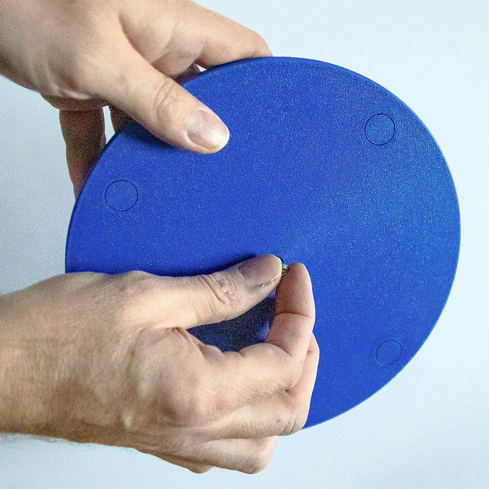
- I. Balance Cap
- J. 12 Springs
- K. 4 Silicone Pads
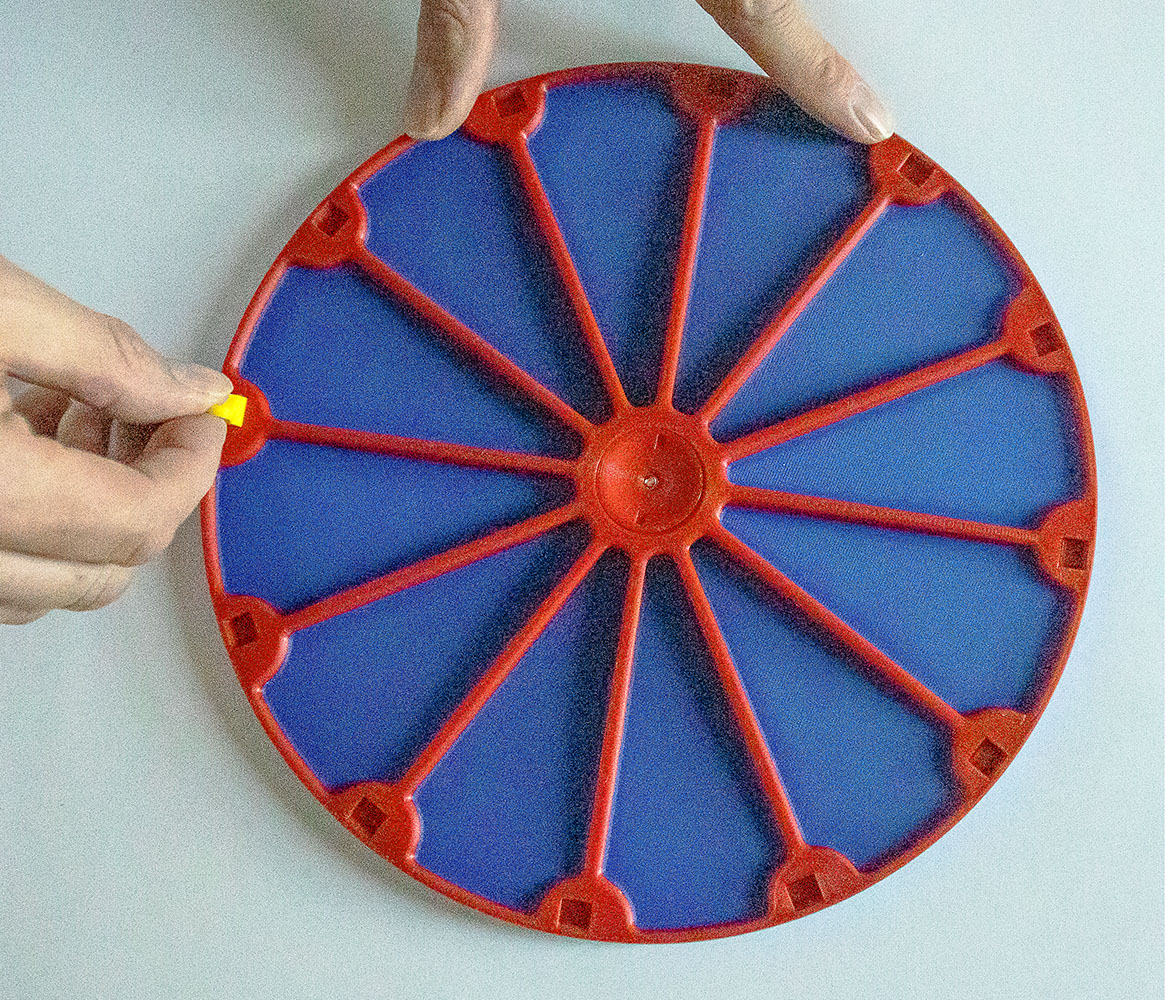
- L. 12 Bottom Platform Hooks for the springs
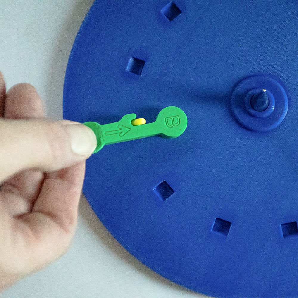
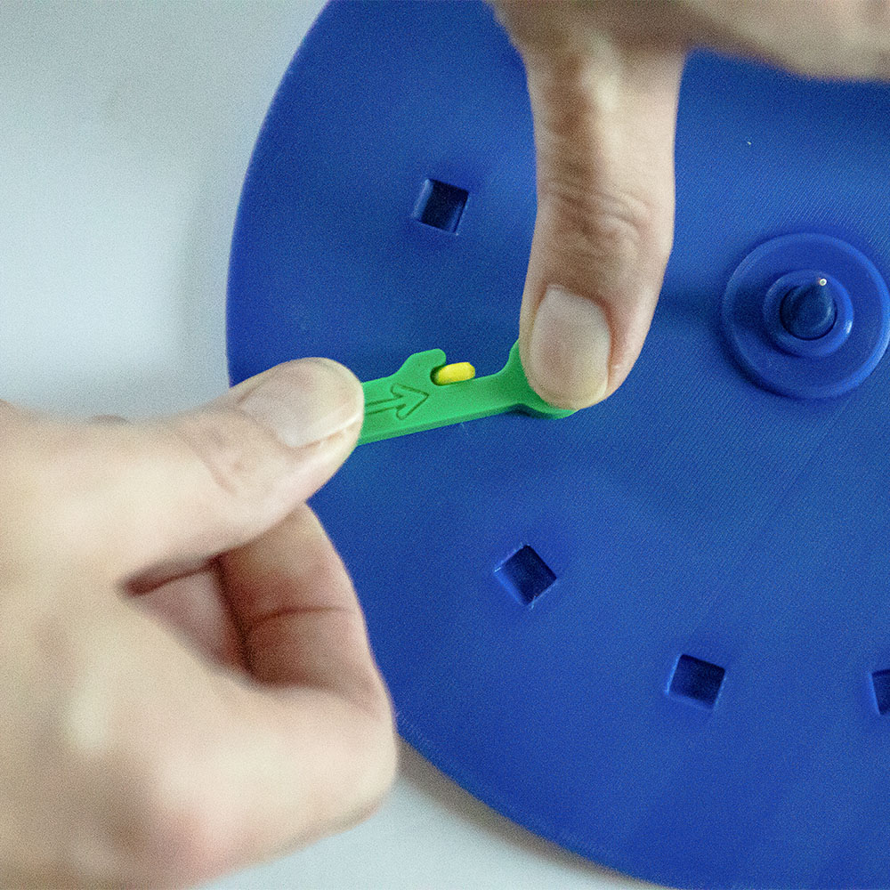
- M. Bottom Platform Hook Insert Tool
- N. Bottom Platform