You’ve read why it works — now here’s what it actually does.
The effectiveness of the SimEyeSee WarpShield was validated using a series of controlled, progressively more demanding
real-world tests designed to replicate common fan-side warping failures.
Tests were performed using both single-color and multi-color prints,
with auxiliary fan levels ranging from 70% to 100%,
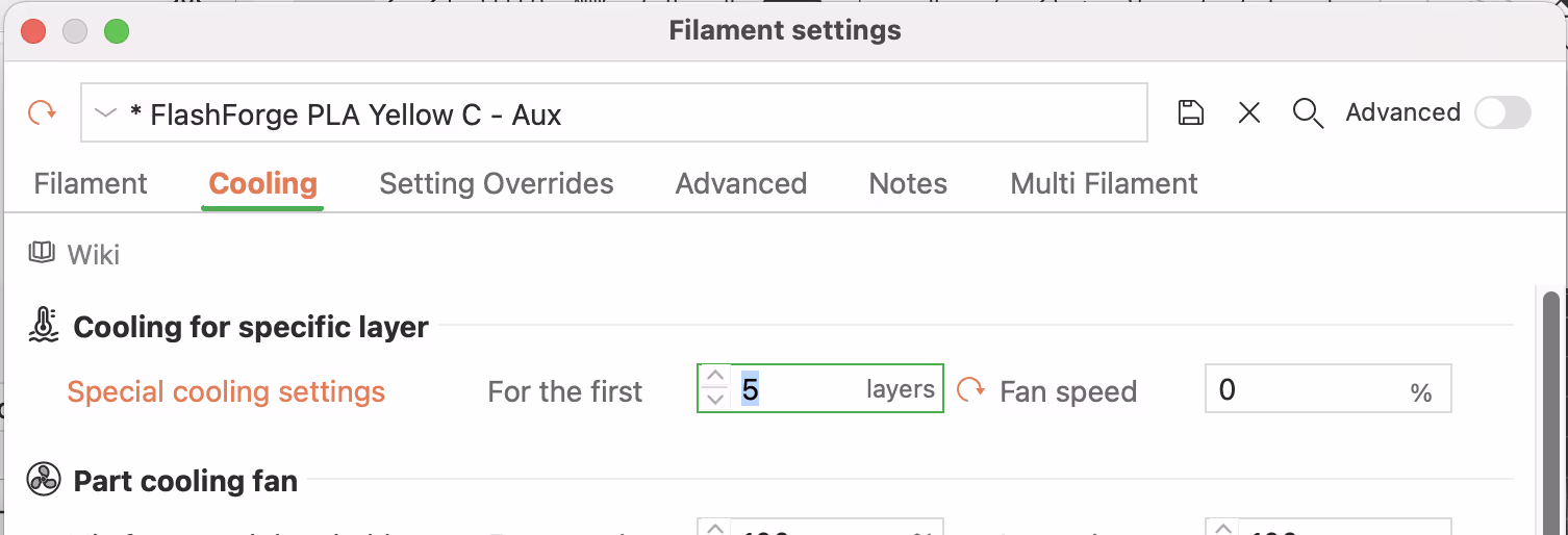
and with the auxiliary fan kept off for the first ~5 layers (1mm) to allow the WarpShield to reach sufficient height
before side airflow was applied.
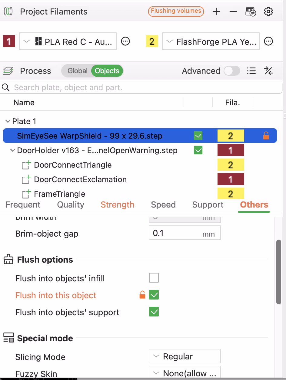
Warping & Failure Comparison — EmBlazeGuard Open Warning Panel
Initial testing used the Open Warning EmBlaze Panel from
EmBlazeGuard,
because it provides real-world geometry that is prone to fan-side warping and can also lift off the bed when the auxiliary fan
overcools the fan-facing lower layers.
The first print was run without a WarpShield at 70% aux fan and exhibited fan-side warping, partial bed lift,
and eventual spaghetti failure. The same panel was then printed again with a Straight WarpShield under identical
conditions and remained flat and stable for the entire print.
This confirms the core behavior: the WarpShield redirects side-blast airflow away from the lower layers where warping begins,
while still allowing strong cooling higher up where it improves surface quality and overhang performance.
Door Angle Stress Tests — EmBlazeGuard Panel
After validating baseline behavior in earlier tests, the Open Warning EmBlaze Panel was tested with the
printer door deliberately angled toward the auxiliary fan to increase direct side airflow onto the part.
This configuration is intentionally aggressive, as the door normally helps deflect some airflow away from the print.
Two multi-color tests were performed with the door angled toward the fan.
The first was printed at 70% auxiliary fan, and the second increased the auxiliary fan to
100% to create a worst-case airflow scenario.
In both cases, the SimEyeSee WarpShield remained effective at redirecting airflow upward,
preventing fan-side warping while allowing the increased cooling to benefit fine details and thin features.
Even at 100% auxiliary fan in a multi-color print — a configuration that would normally
cause early-layer warping or lifting — the WarpShield maintained stability on the fan-facing side.
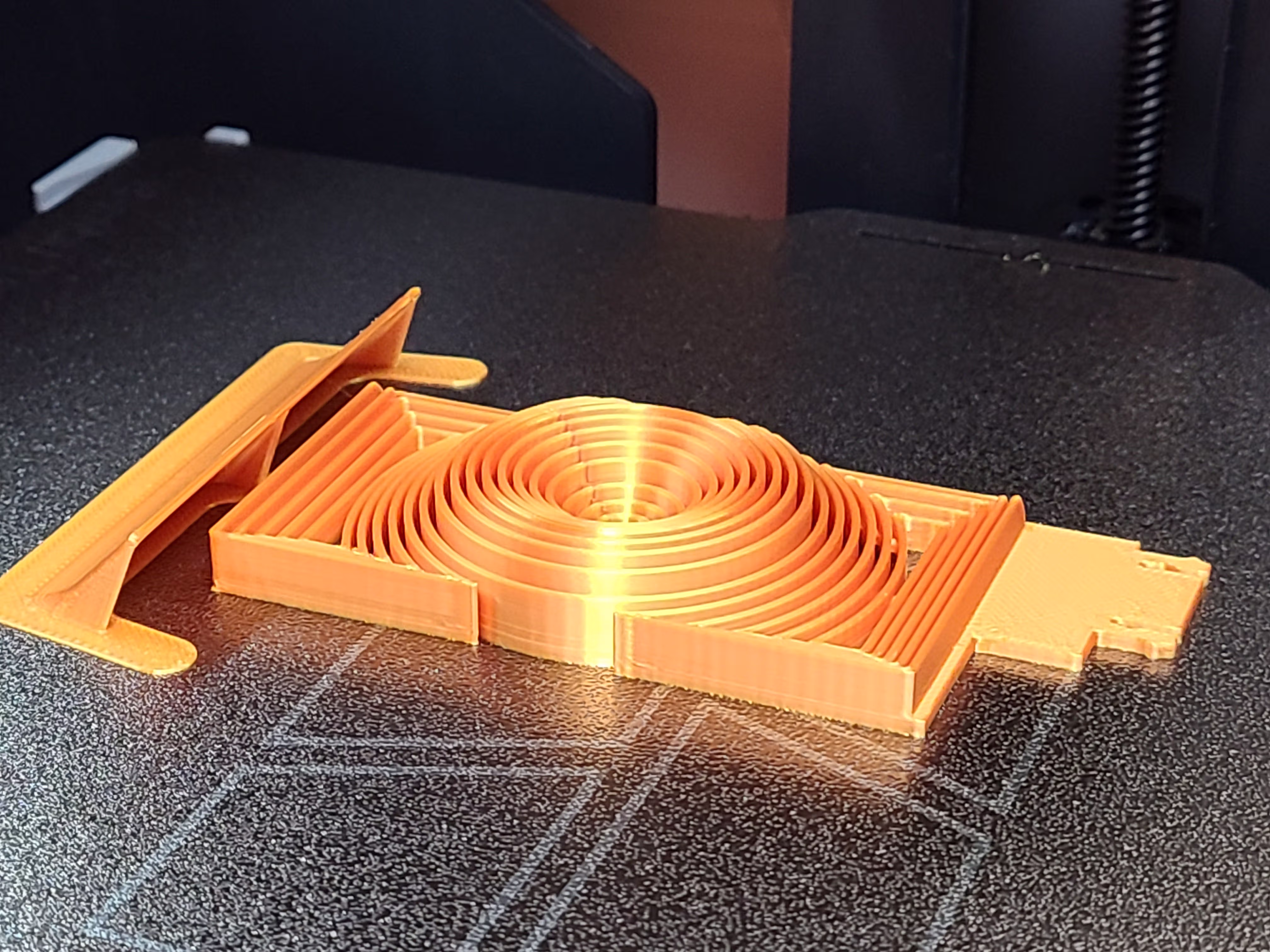
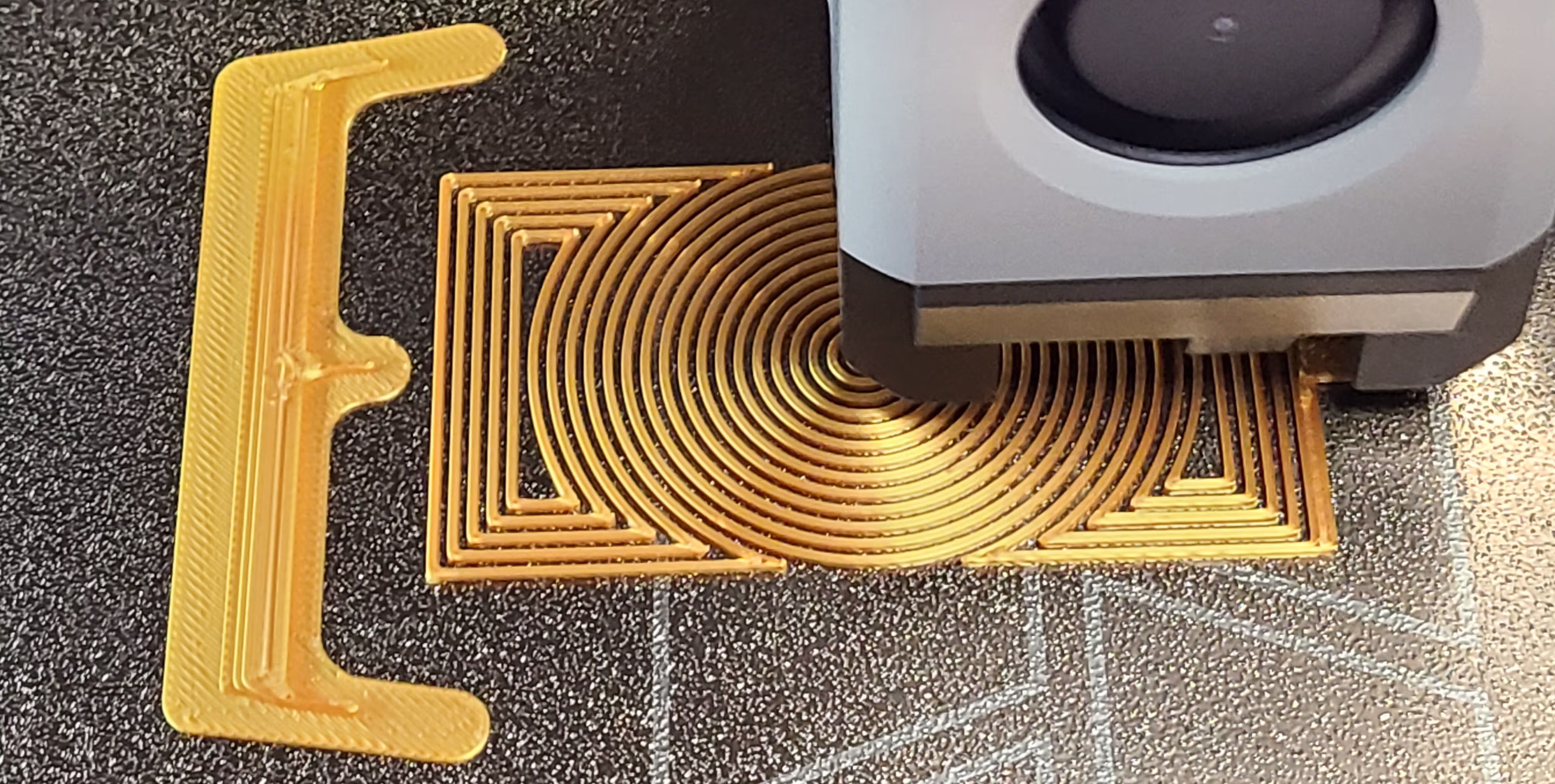
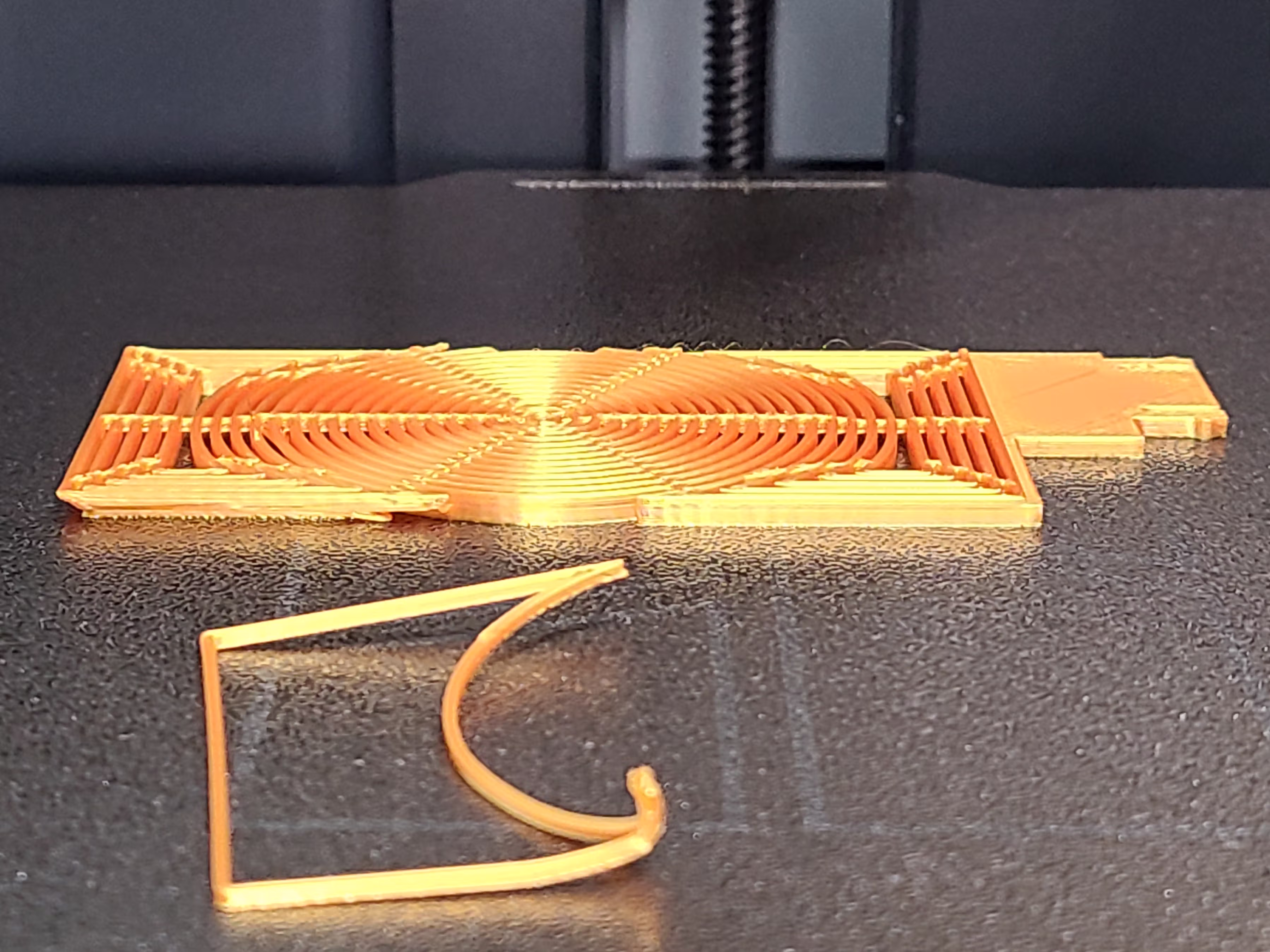
Vortex-Matrix Thin-Wall Stress Test — EmBlazeGuard Panel
Another demanding validation was performed using the
EmBlazeGuard Vortex-Matrix Panel,
a design composed of many 0.84 mm thin walls arranged in a dense, open structure.
This geometry is highly sensitive to fan-side cooling but also benefits from strong auxiliary airflow
to print cleanly due to its thin features.

The panel was first printed without a WarpShield at 70% auxiliary fan,
where fan-side lifting and warping appeared early in the print.
The same part was then printed again with a Straight WarpShield placed on the auxiliary-fan side.
With the WarpShield in place, the panel remained fully flat and stable throughout the print —
not only at 70%, but also when the auxiliary fan was increased to
100%.
No fan-side lift, base distortion, or wall deformation was observed,
even under maximum side cooling.
This test demonstrates an important use case for the WarpShield:
enabling aggressive auxiliary cooling on thin-wall parts
without sacrificing bed adhesion.
In designs like the Vortex-Matrix panel, the WarpShield allows cooling to be increased
to meet feature-quality requirements while still protecting the lower layers
where warping typically begins.
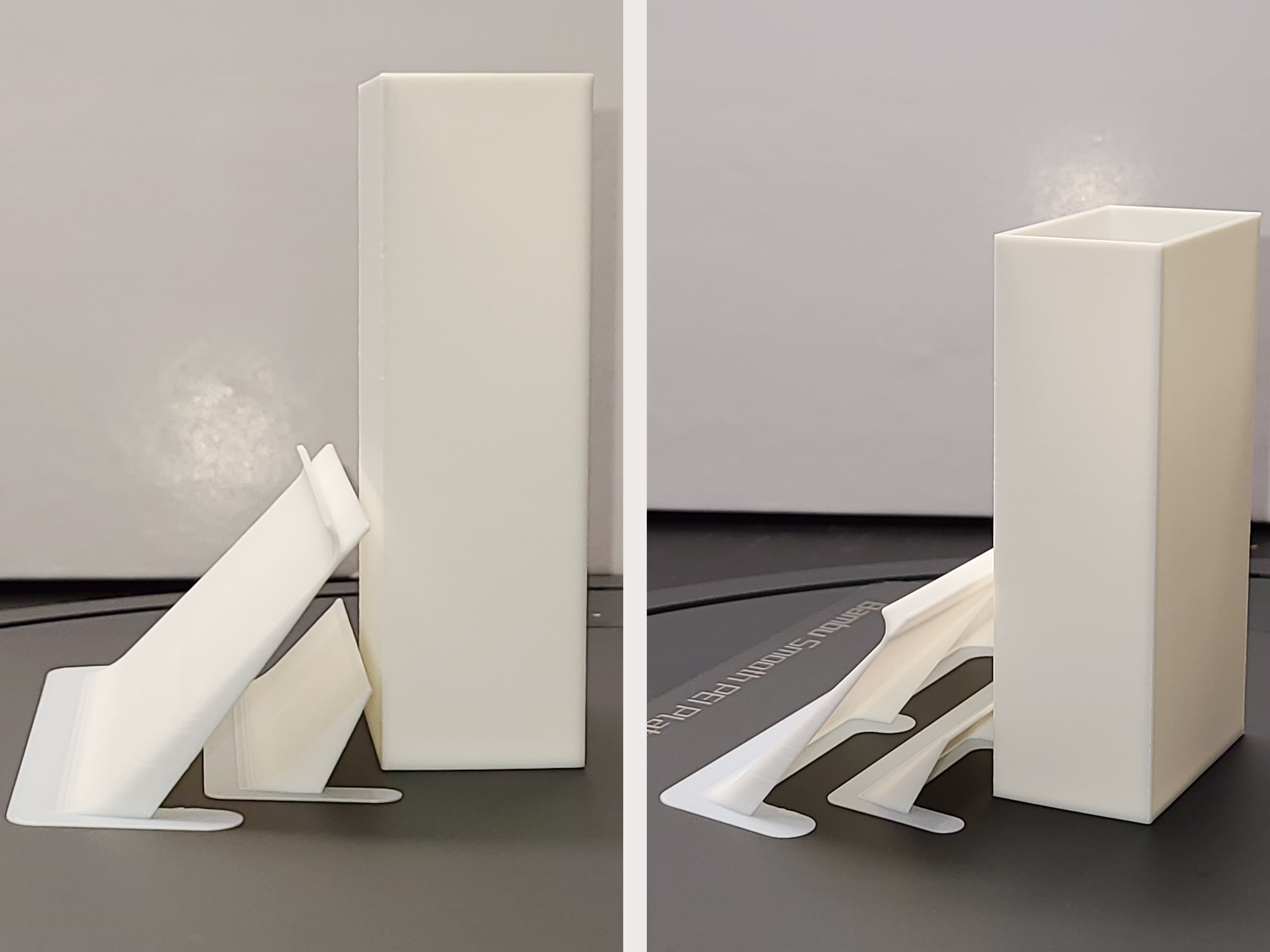
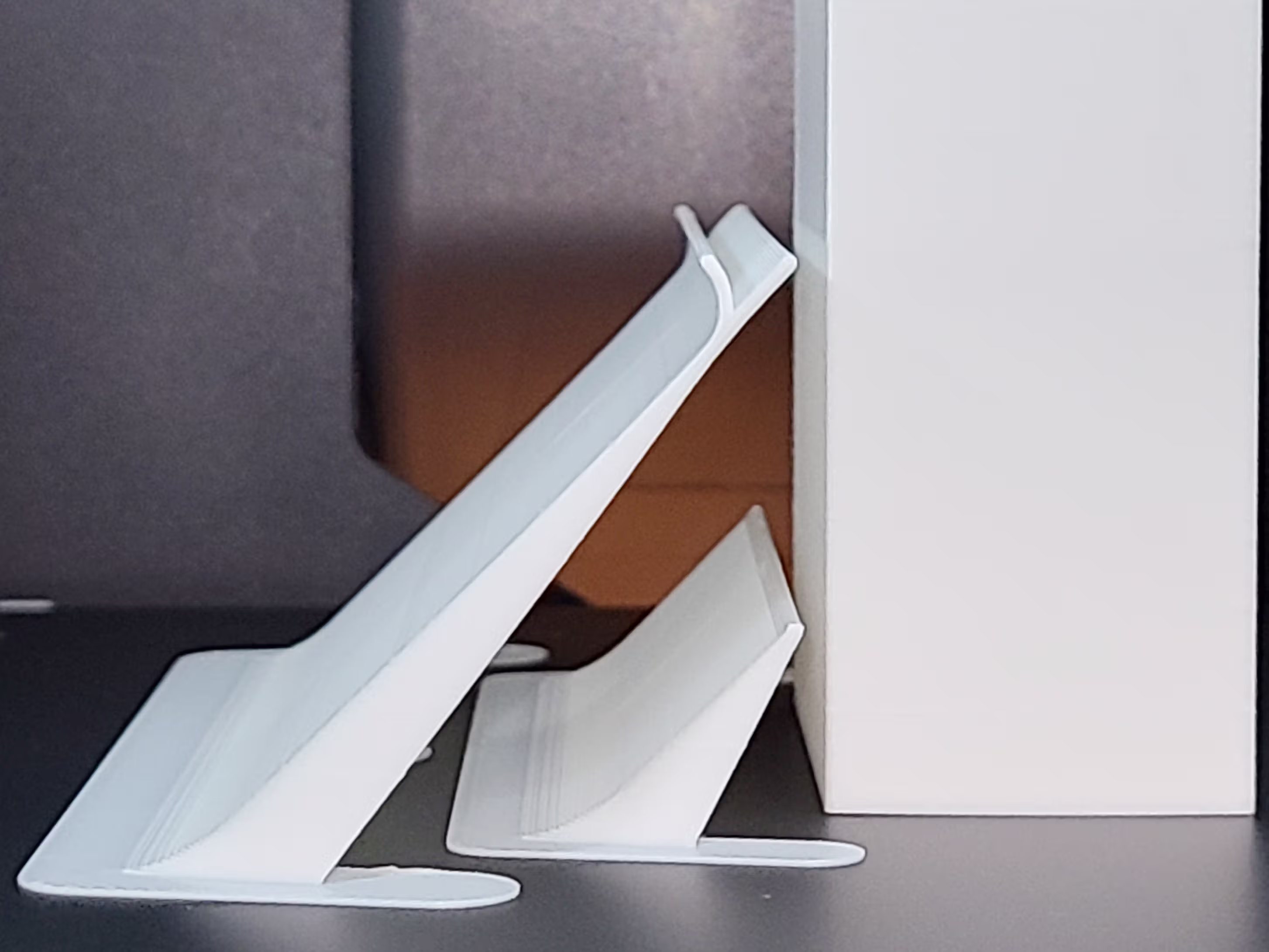
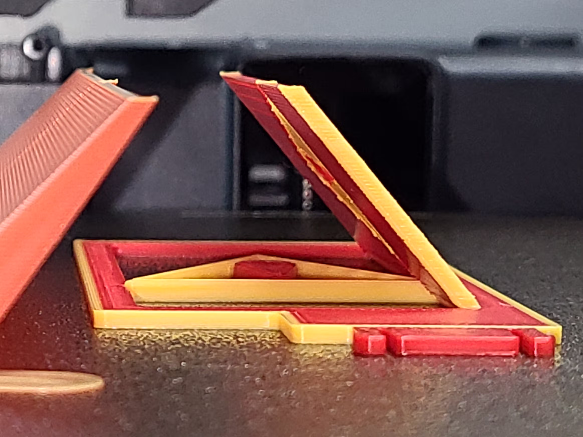
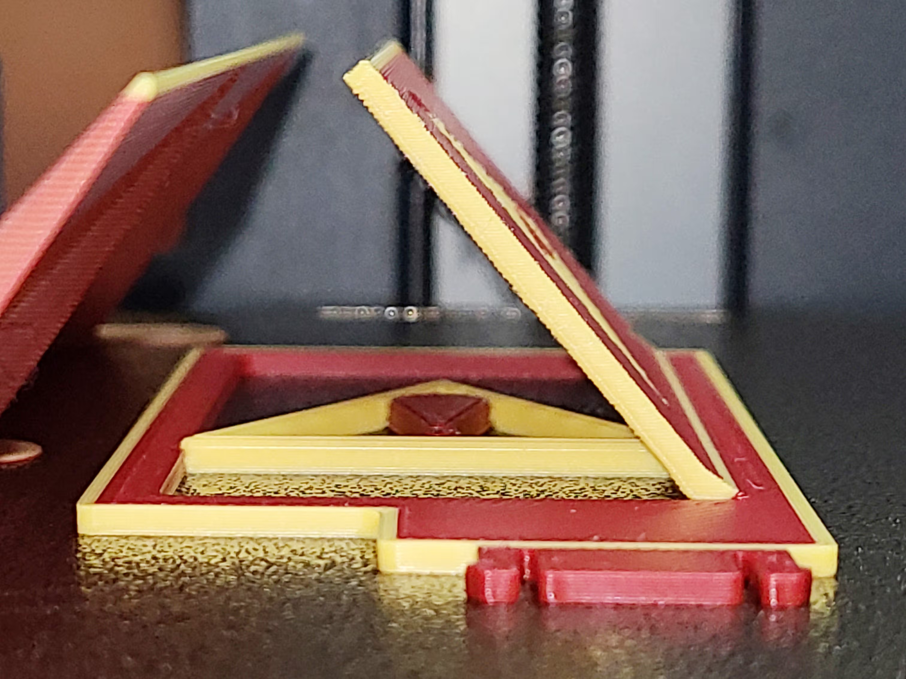
Tall Part Validation — Curved + Straight Starter WarpShields
A tall, thin-walled test part was used because this geometry is naturally prone to fan-induced warping and bed lift.
In the unshielded case, warping initiated early and progressed along multiple edges simultaneously —
including the fan-facing side, adjacent corners, and the front edge — indicating widespread overcooling of the
lower layers.
The tall-part tests compared no WarpShield versus Curved + Straight Starter WarpShields.
With both shields in place, the base remained flat throughout the print, demonstrating effective
airflow redirection during the most warp-sensitive early layers.
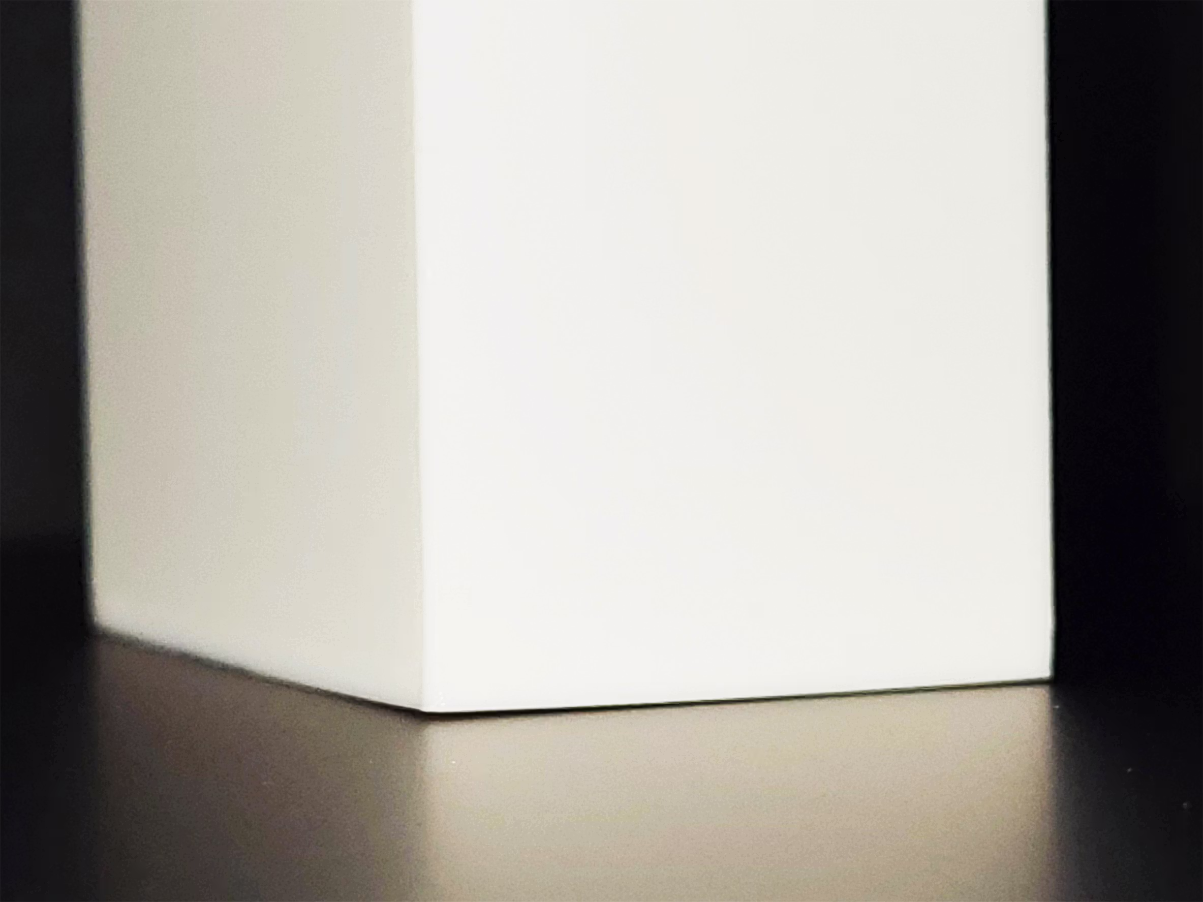
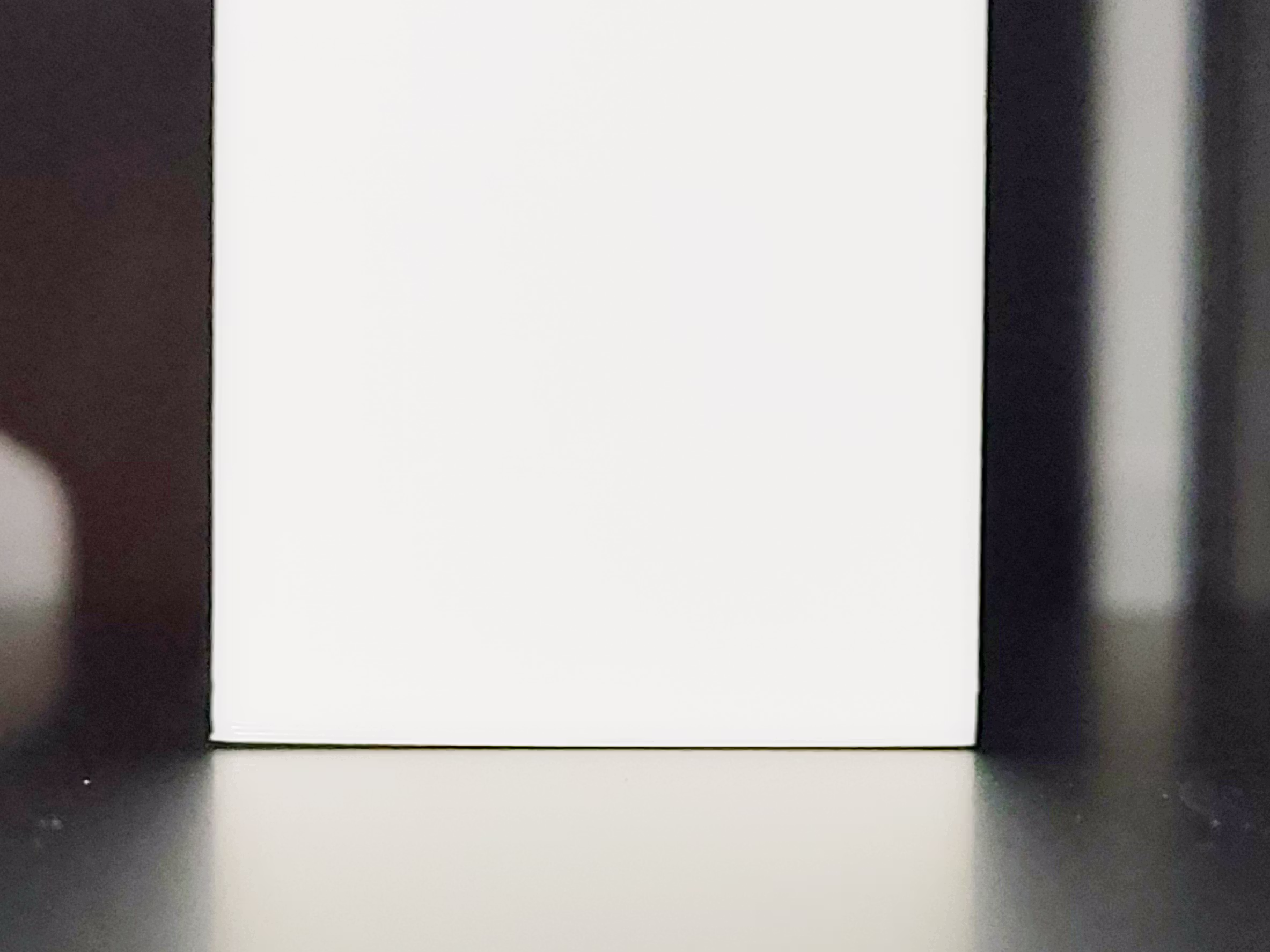
Full-Width Edge Test — Straight WarpShield
A full-width Straight WarpShield with partWidth = 160 mm and partHeight = 40 mm
(resulting in a shield approximately 225 mm wide and 40 mm tall)
was generated to be as wide as possible while still avoiding the non-printable area
at the front-left corner of the build plate.
The shield was then placed 0.5 mm from the auxiliary-fan-side edge of the build plate.
The test was performed at 70% auxiliary fan.


Even in this configuration — with the WarpShield positioned extremely close to the auxiliary fan
and just 0.5 mm from the edge of the build plate —
the shield remained stable with no warping of the wall.
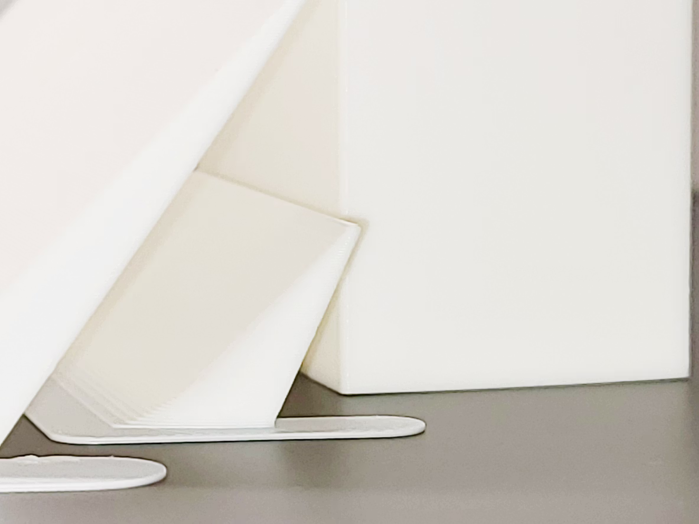
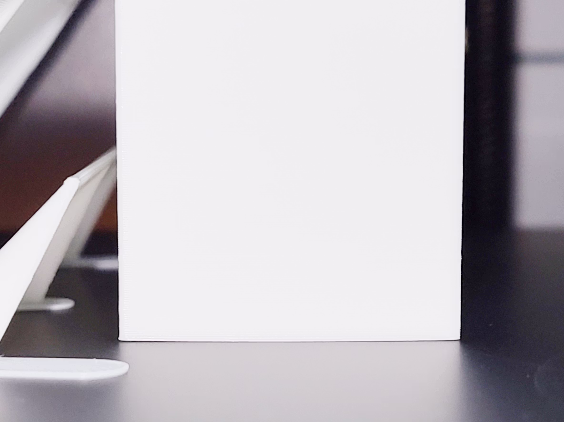
Brim lift was visible on the fan side, but it did not propagate into the part
or worsen as the print progressed.
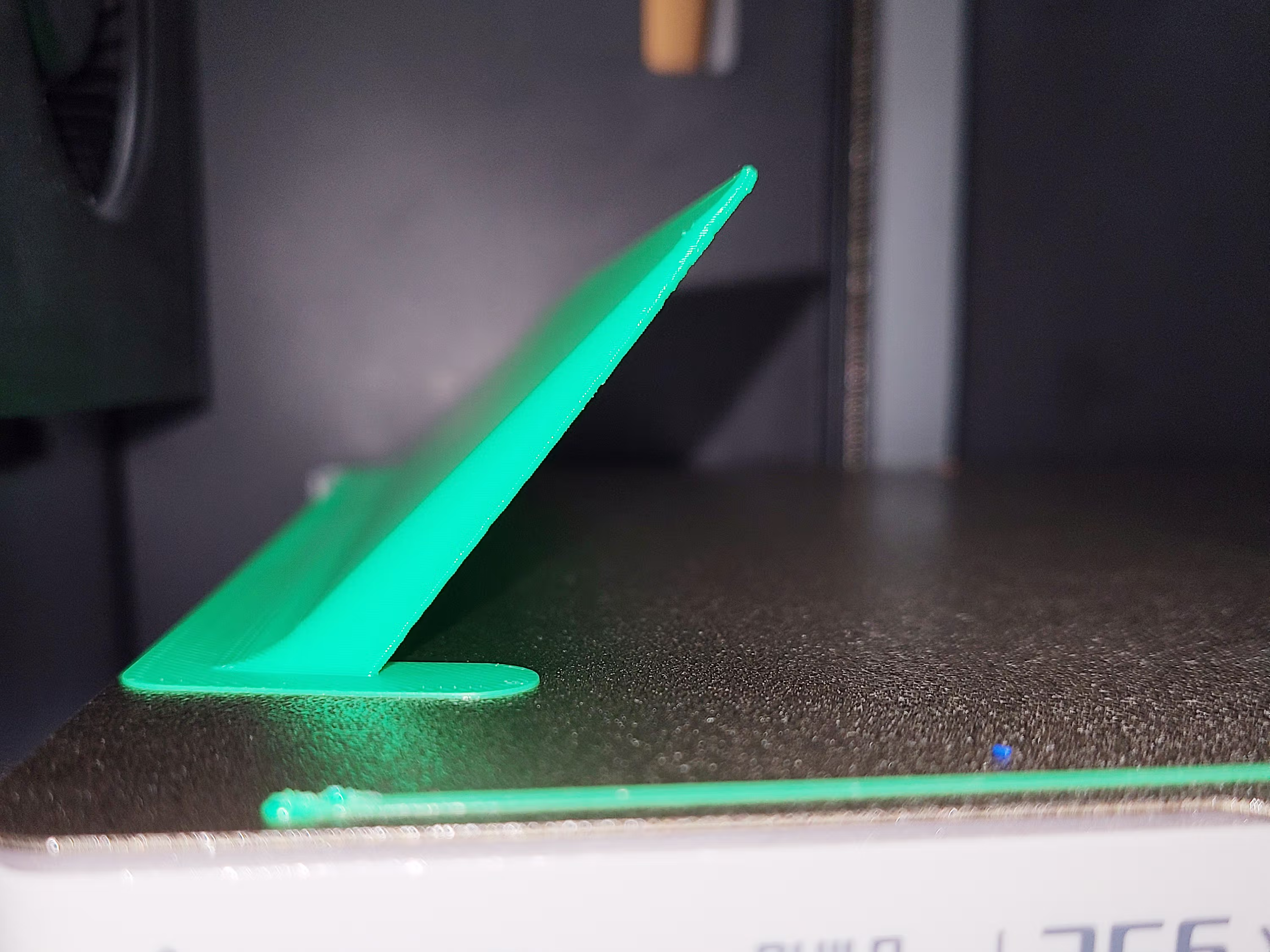
Why this matters: The WarpShield’s angled geometry redirects the auxiliary fan’s airflow upward,
reducing the tendency for airflow to be driven downward into the first layers — which is what typically
causes peeling and warping on fan-facing parts.
Back to Top
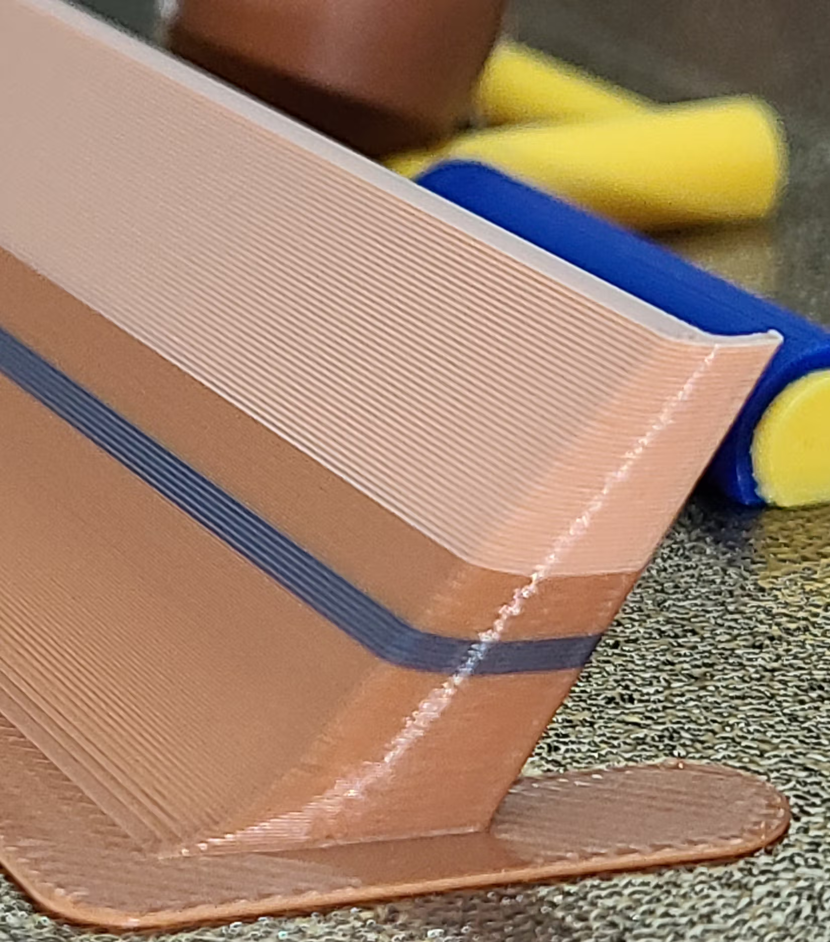
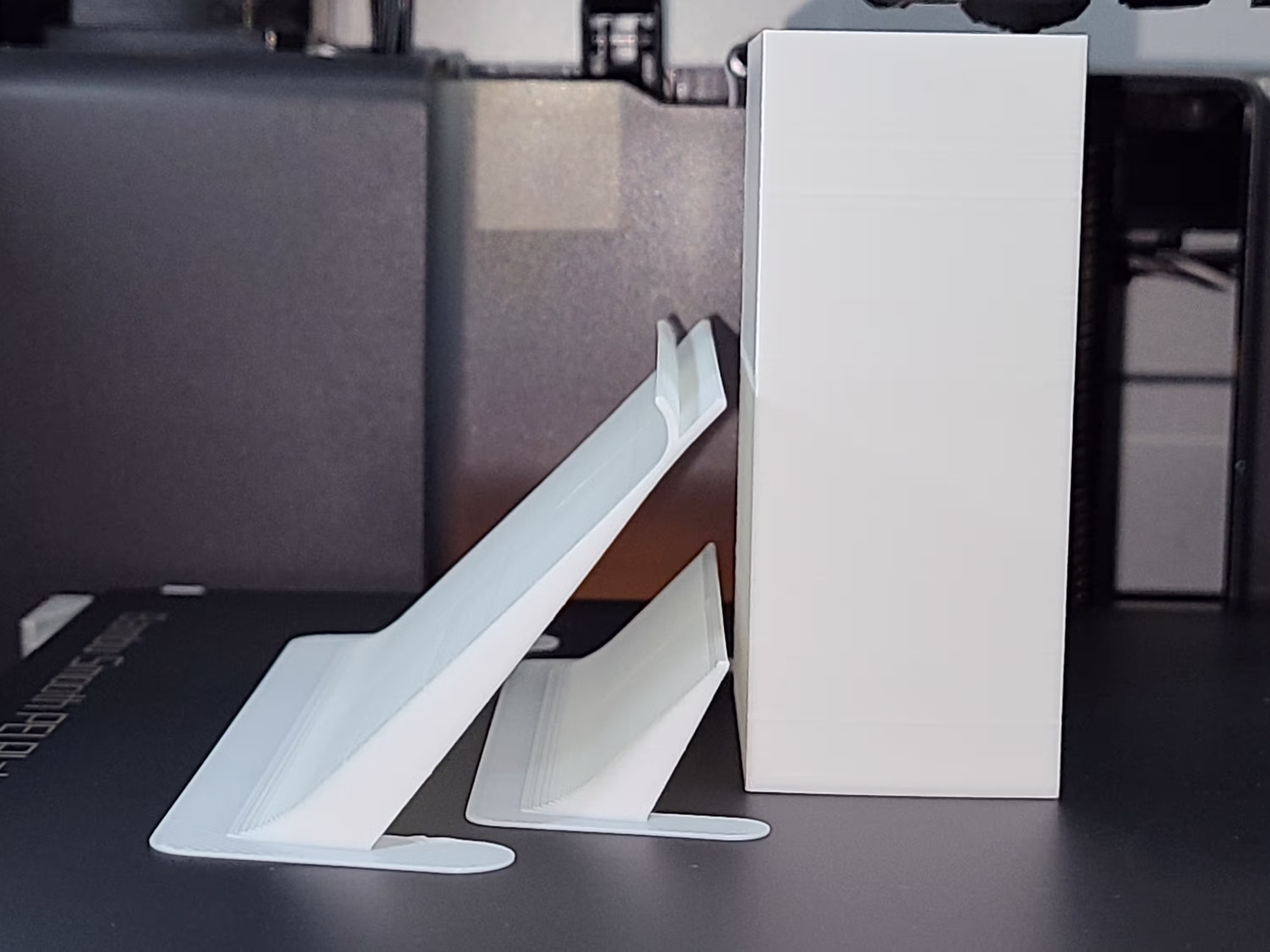 Curved and Straight Starter WarpShield protecting a tall part
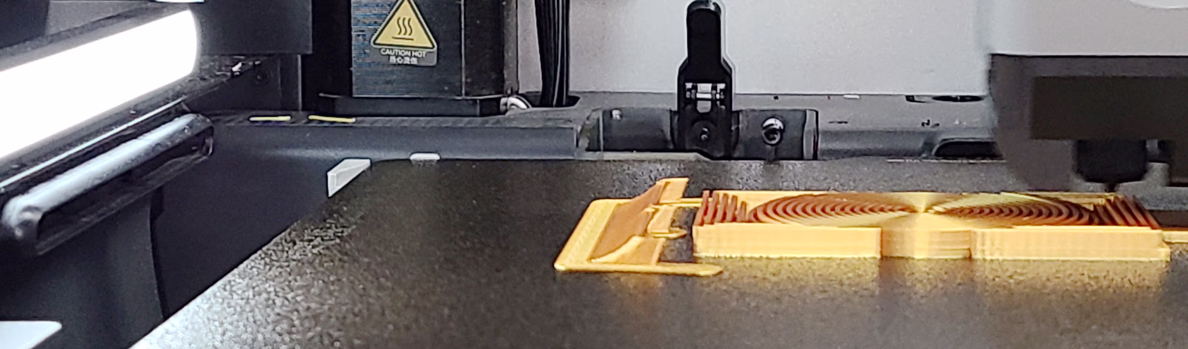
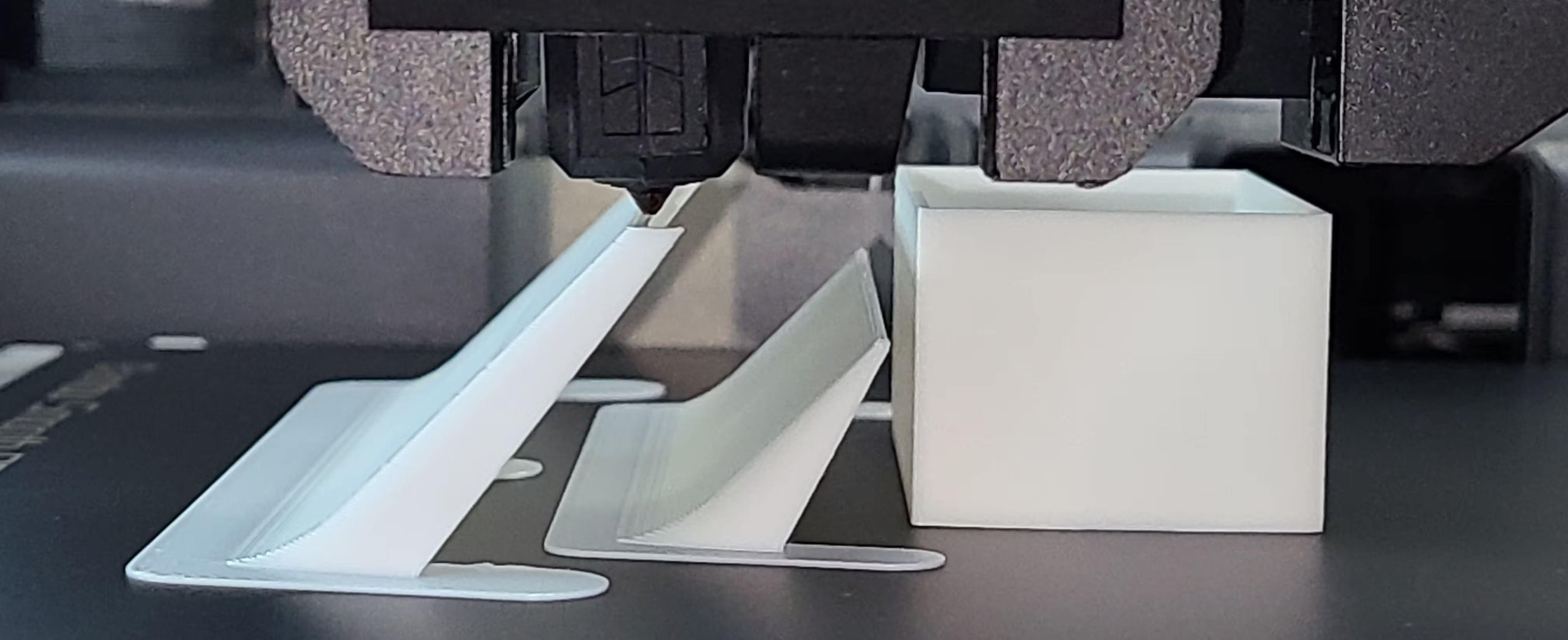
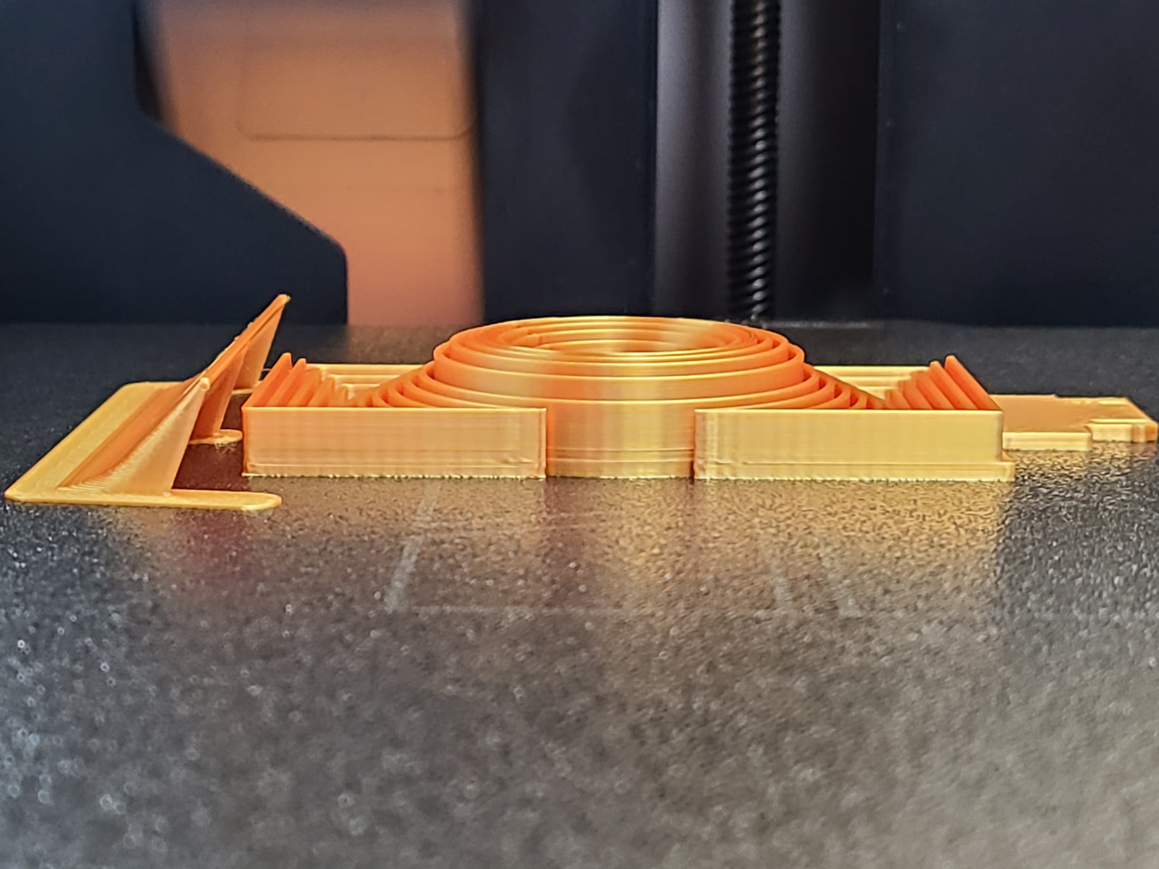
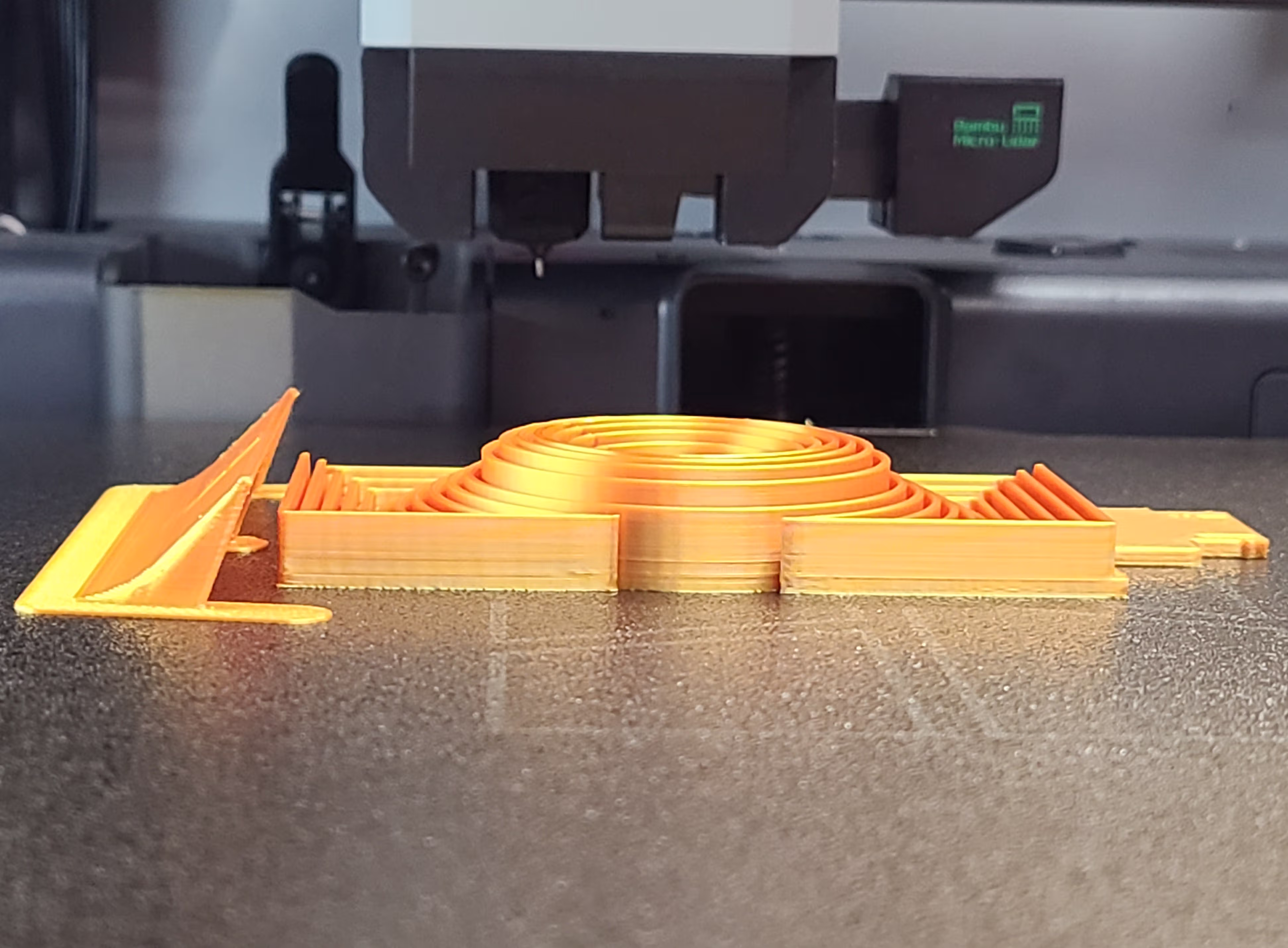
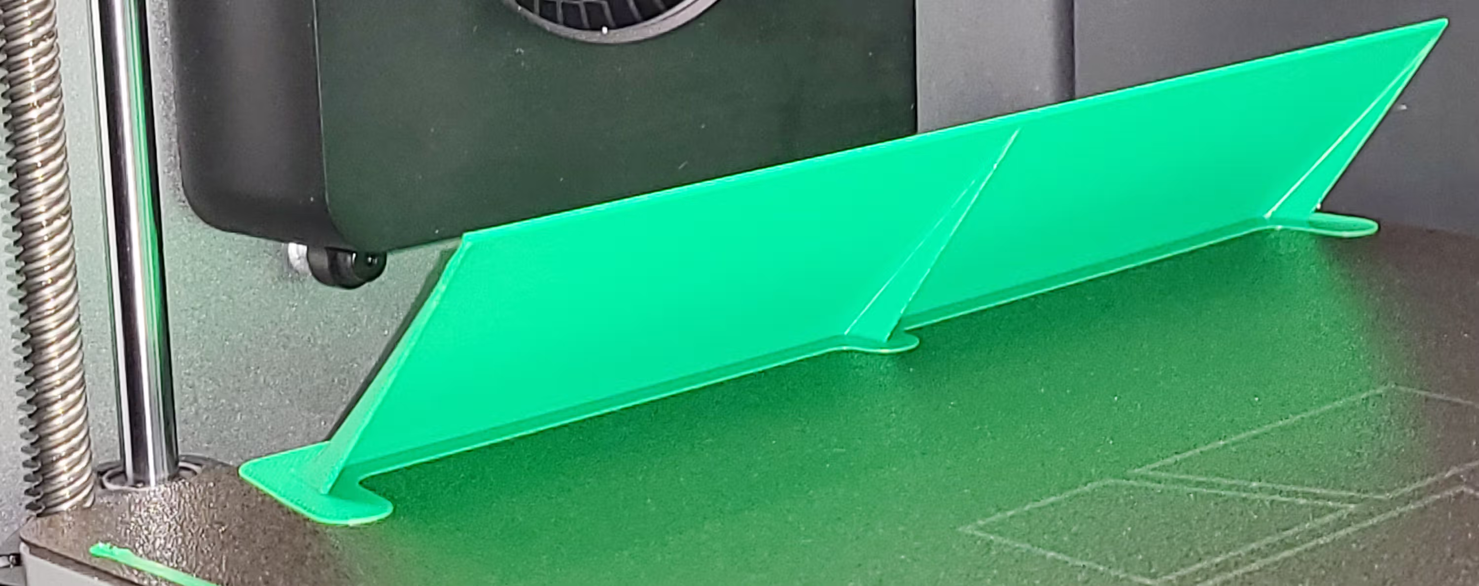
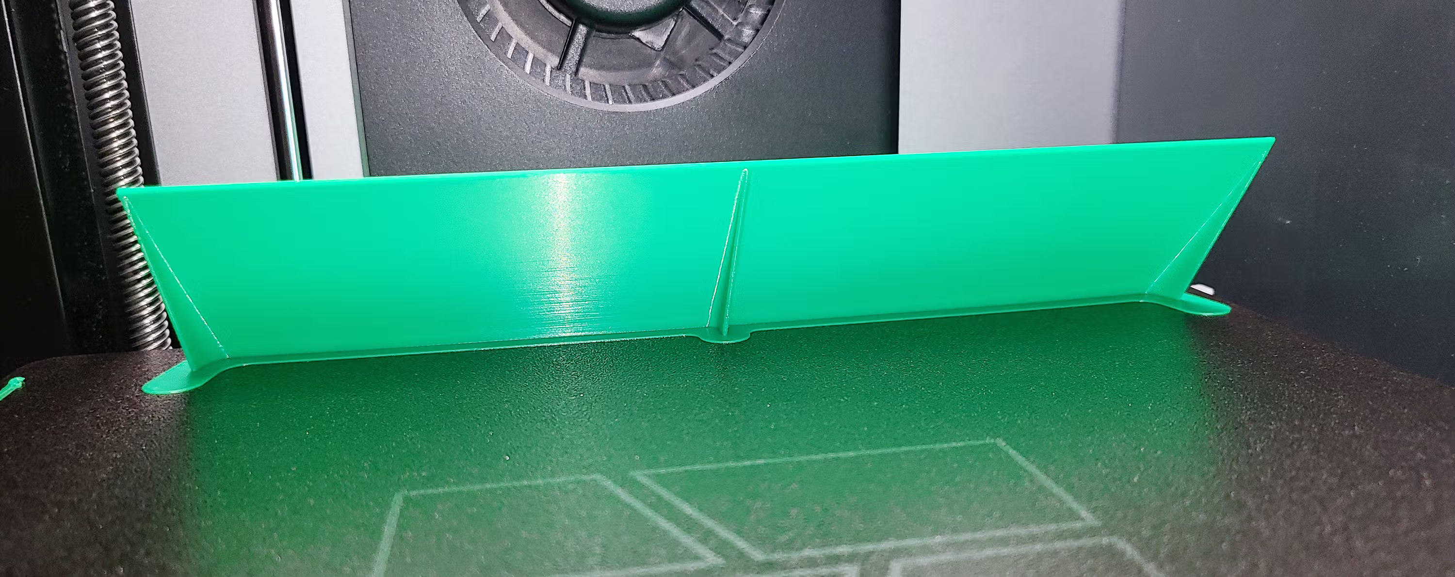
 Single Straight WarpShield while printing
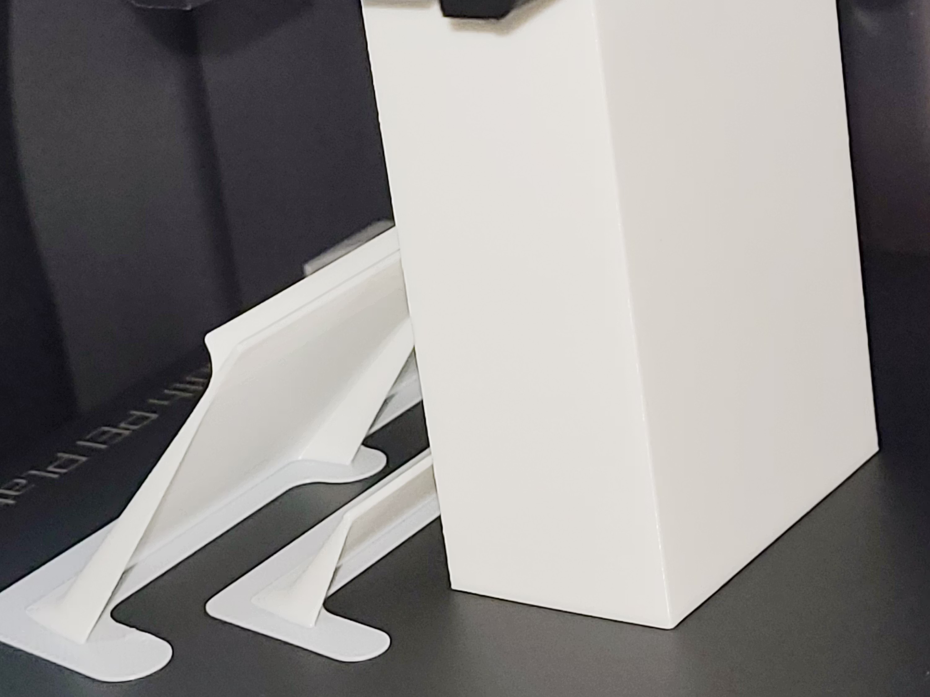
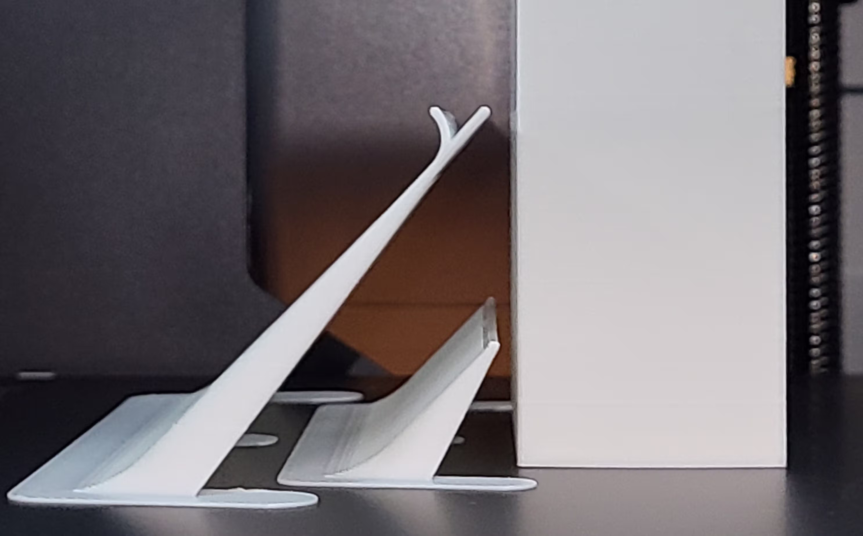 Curved and Straight Starter WarpShields positioned 2 mm from the tall test part
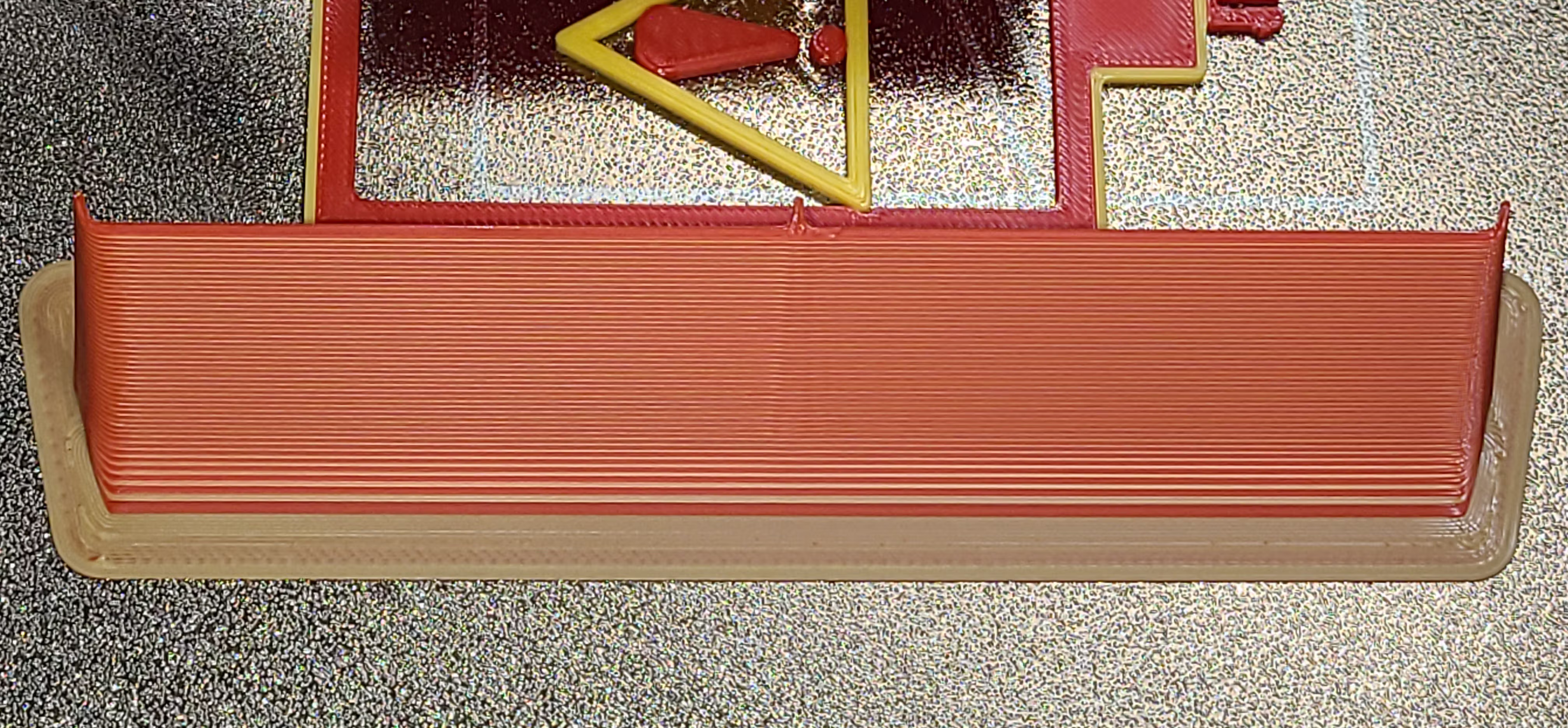
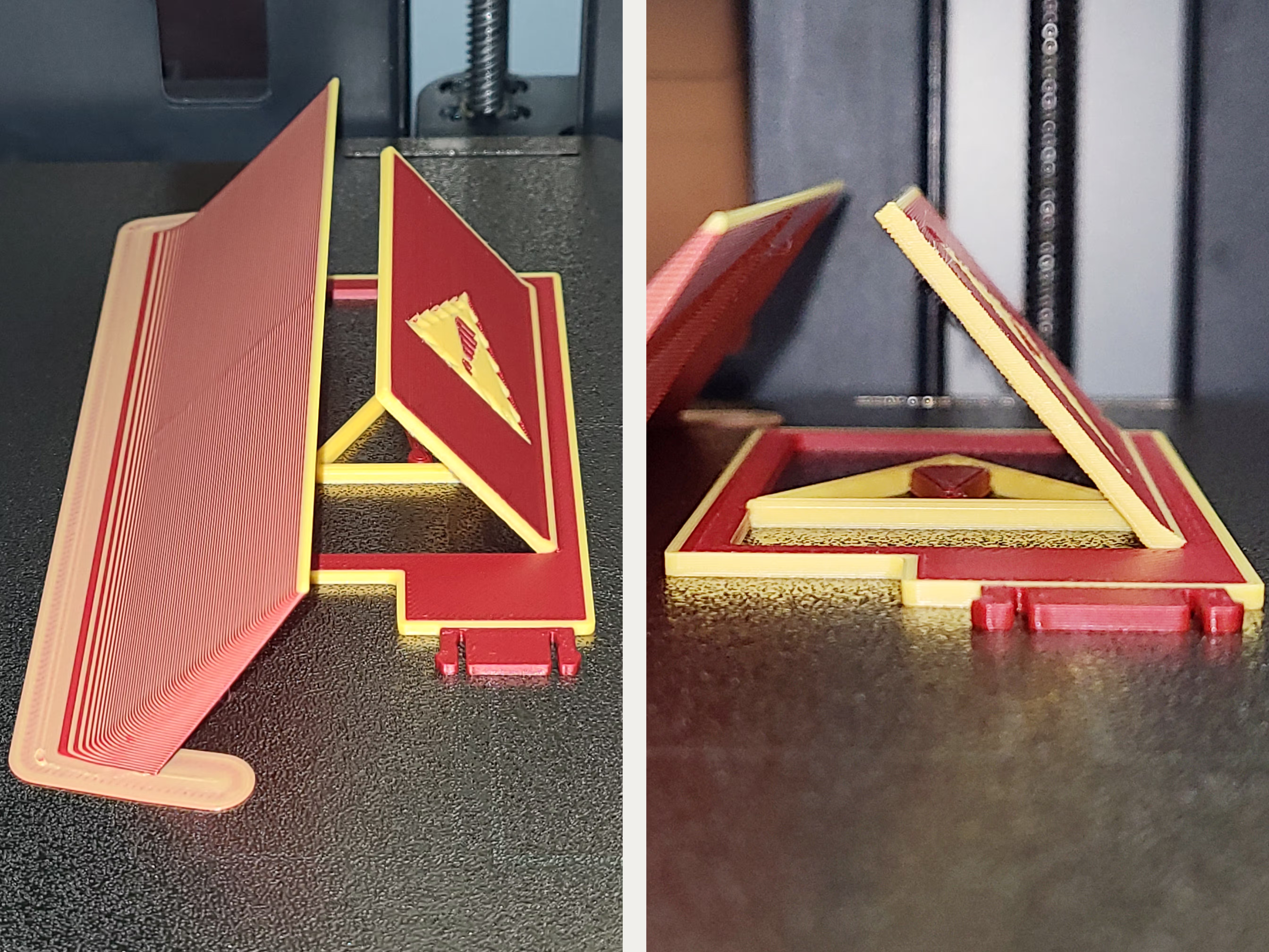 Straight WarpShield
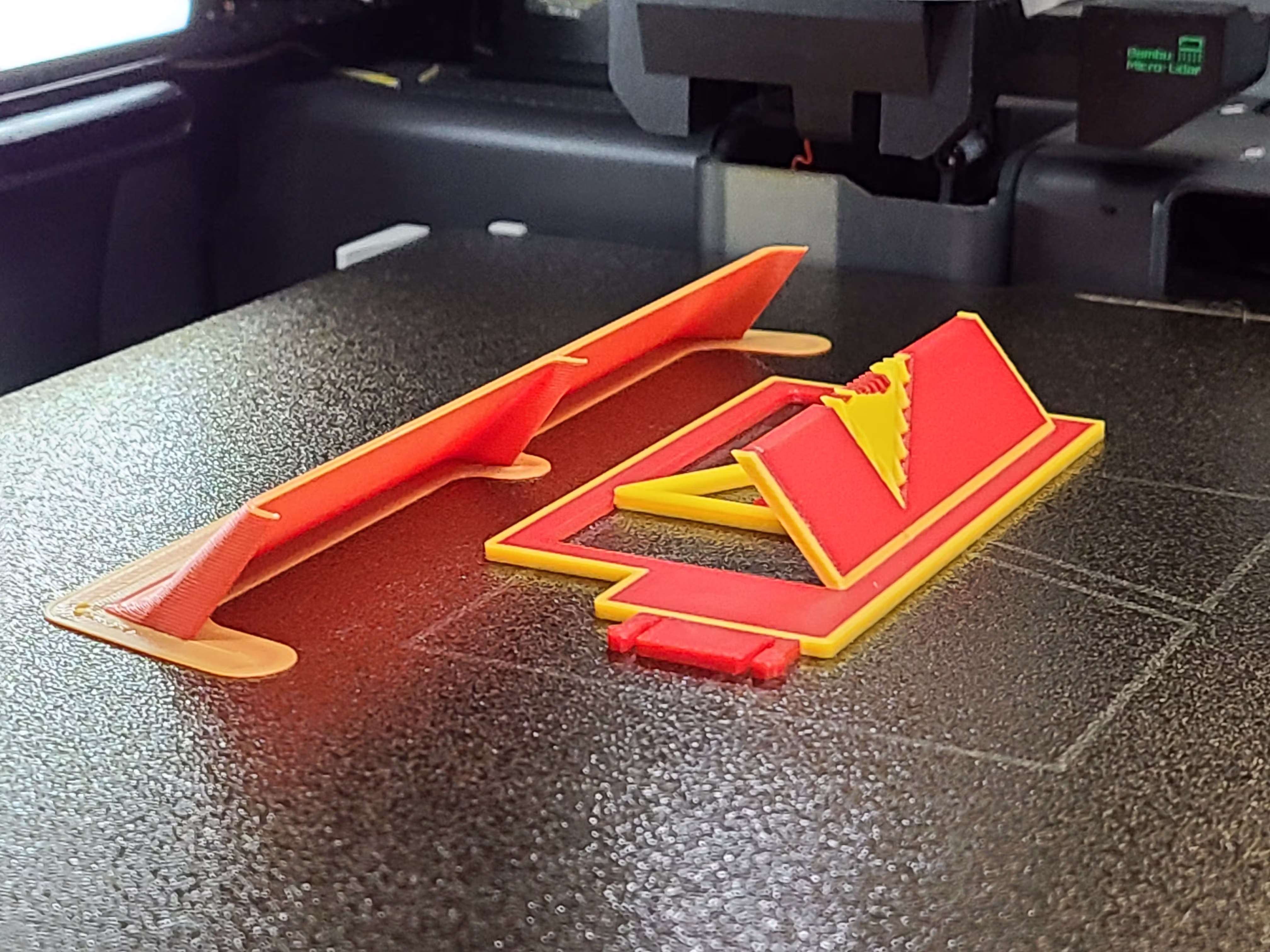
 Curved and Straight WarpShield
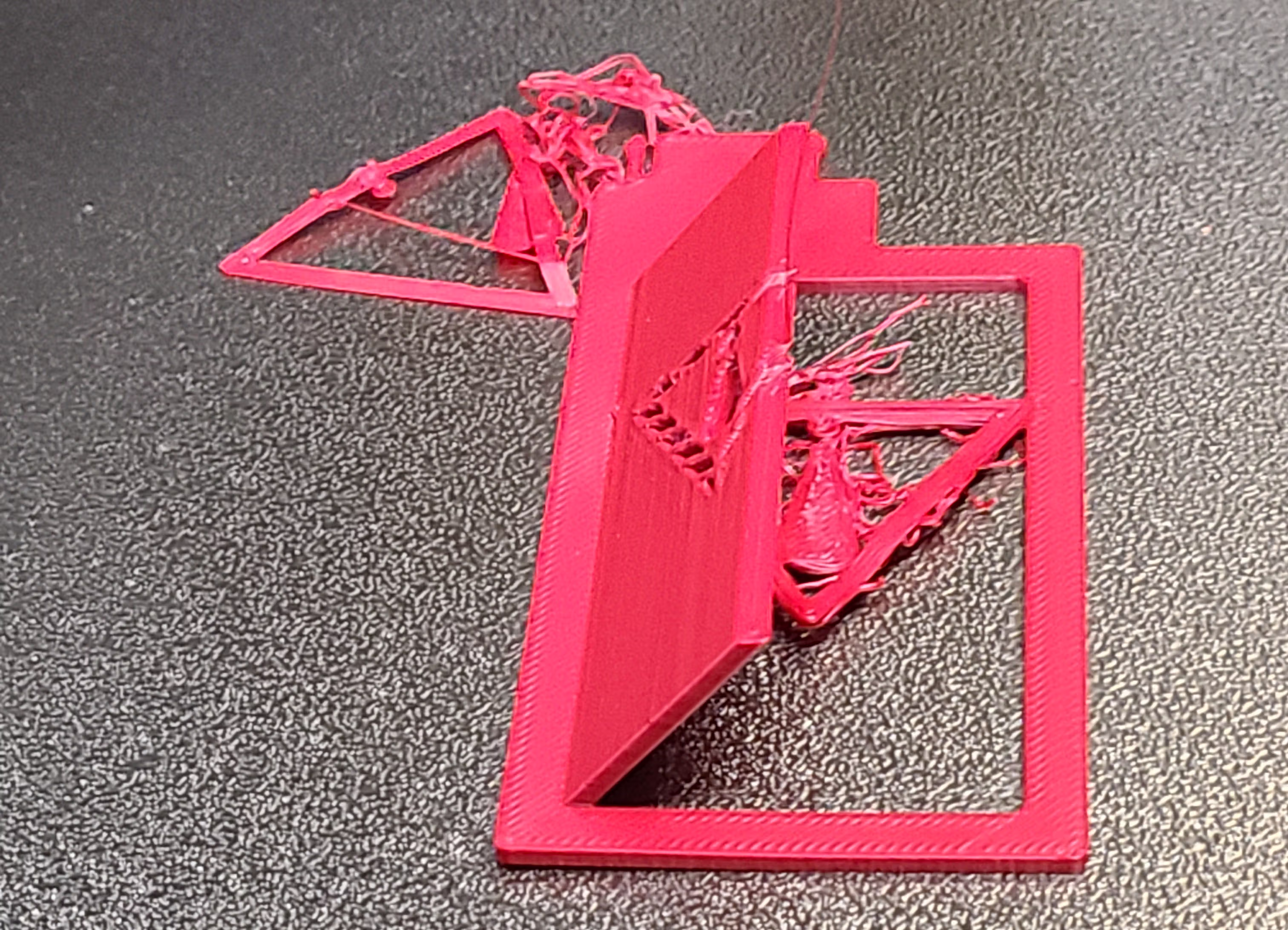 No WarpShield at 70% Auxiliary Fan
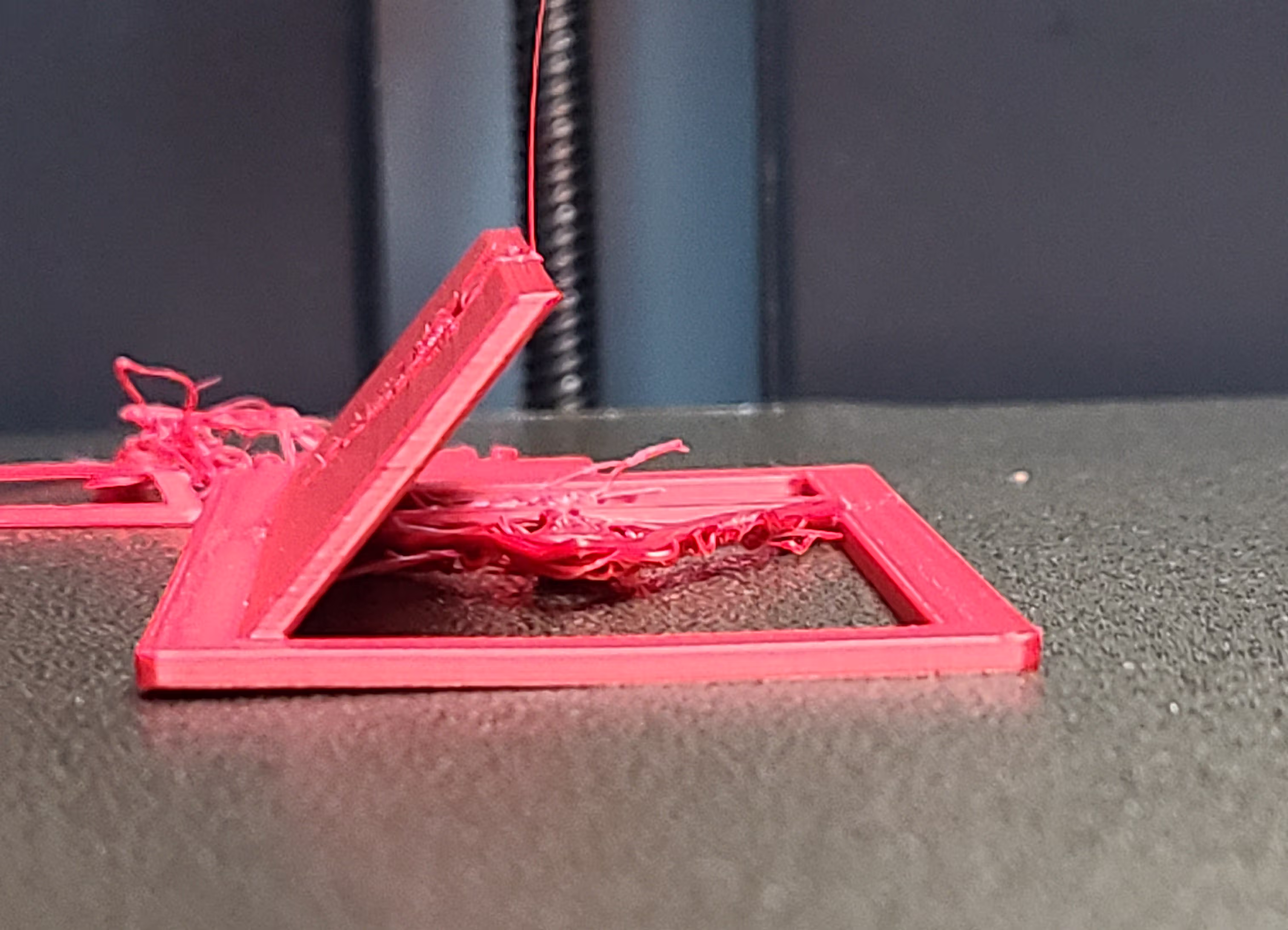 Fan-side warping and bed lift
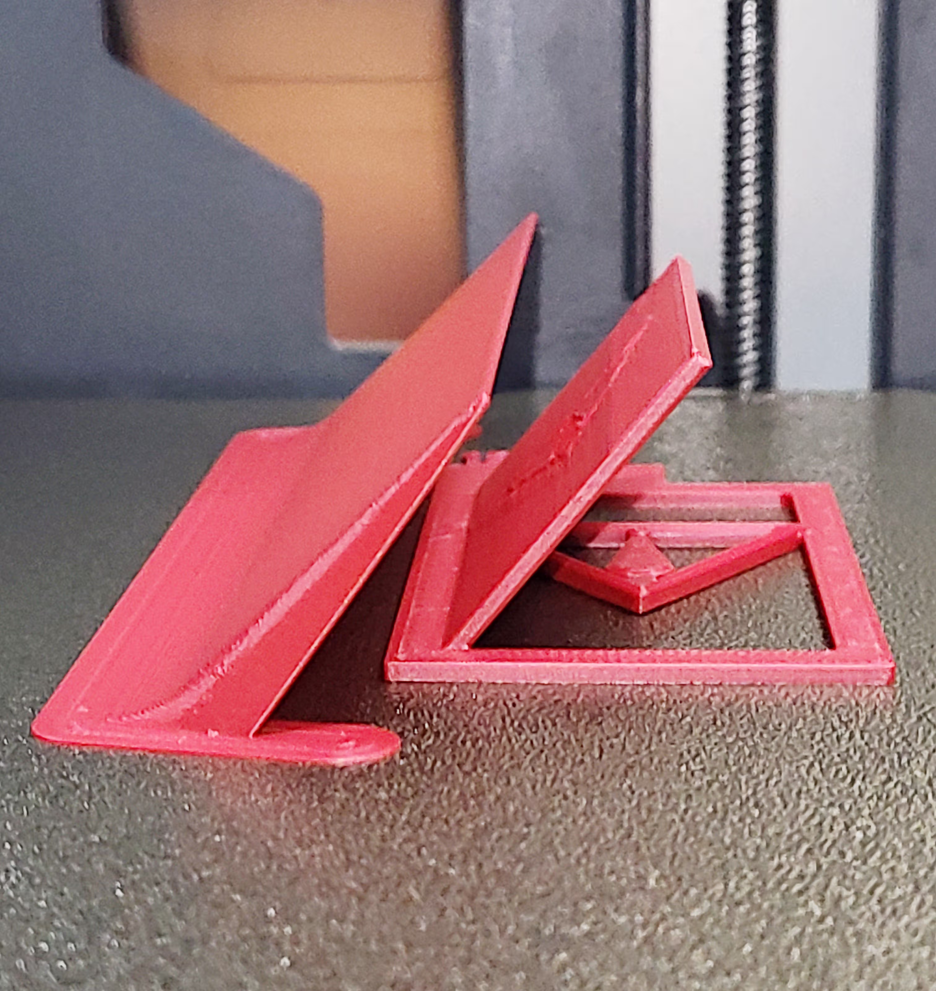 WarpShield at 70% Auxiliary Fan
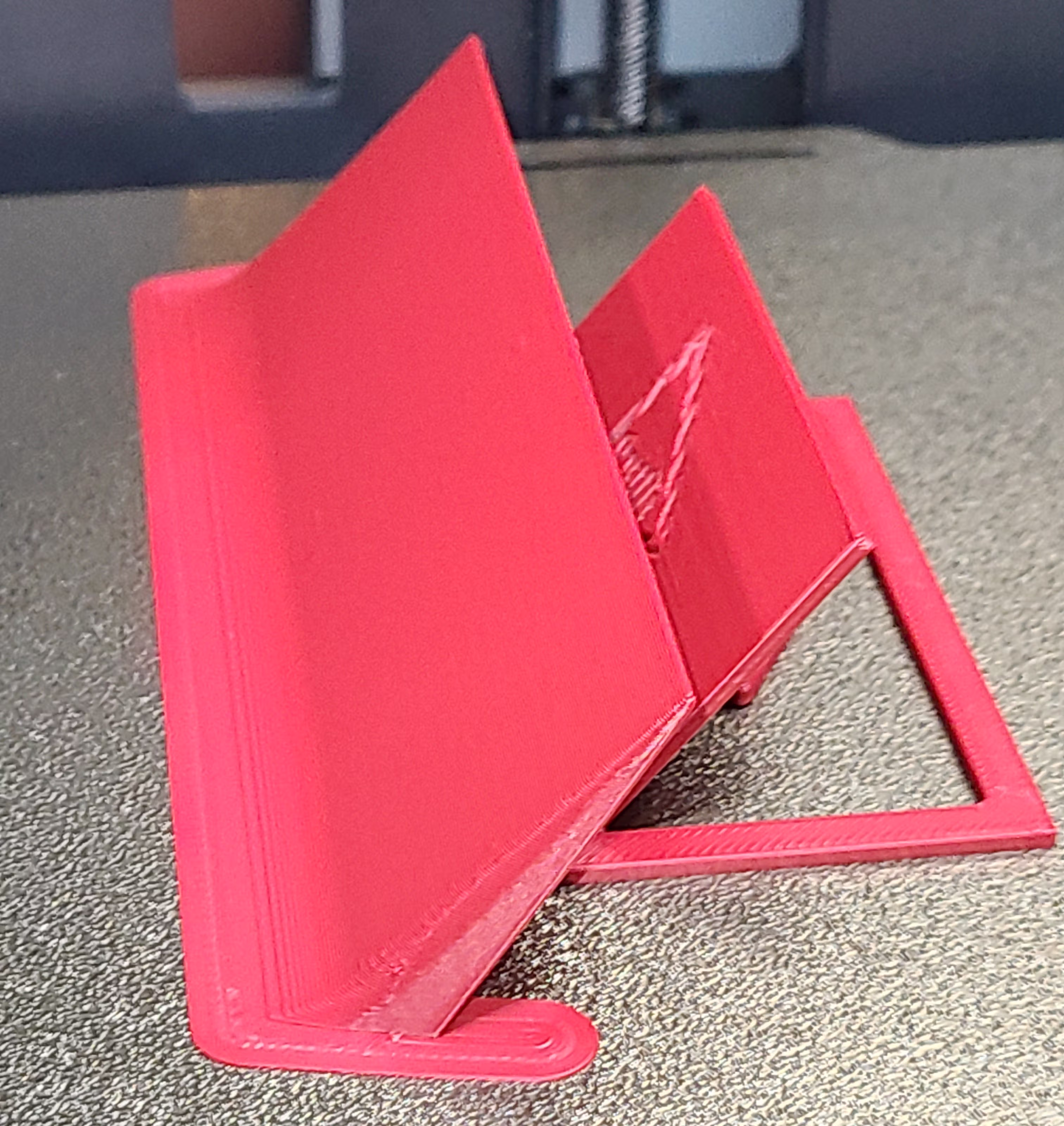 No warping, remains flat and stable
 WarpShield at 70% Auxiliary Fan
 WarpShield at 100% Auxiliary Fan
 No WarpShield at 70% Auxiliary Fan
 WarpShield at 70% Auxiliary Fan
 WarpShield at 100% Auxiliary Fan
 No WarpShield Left Corner
 WarpShield Left Corner
 No WarpShield Front
 WarpShield Front
 No WarpShield Right Corner
 WarpShield Right Corner
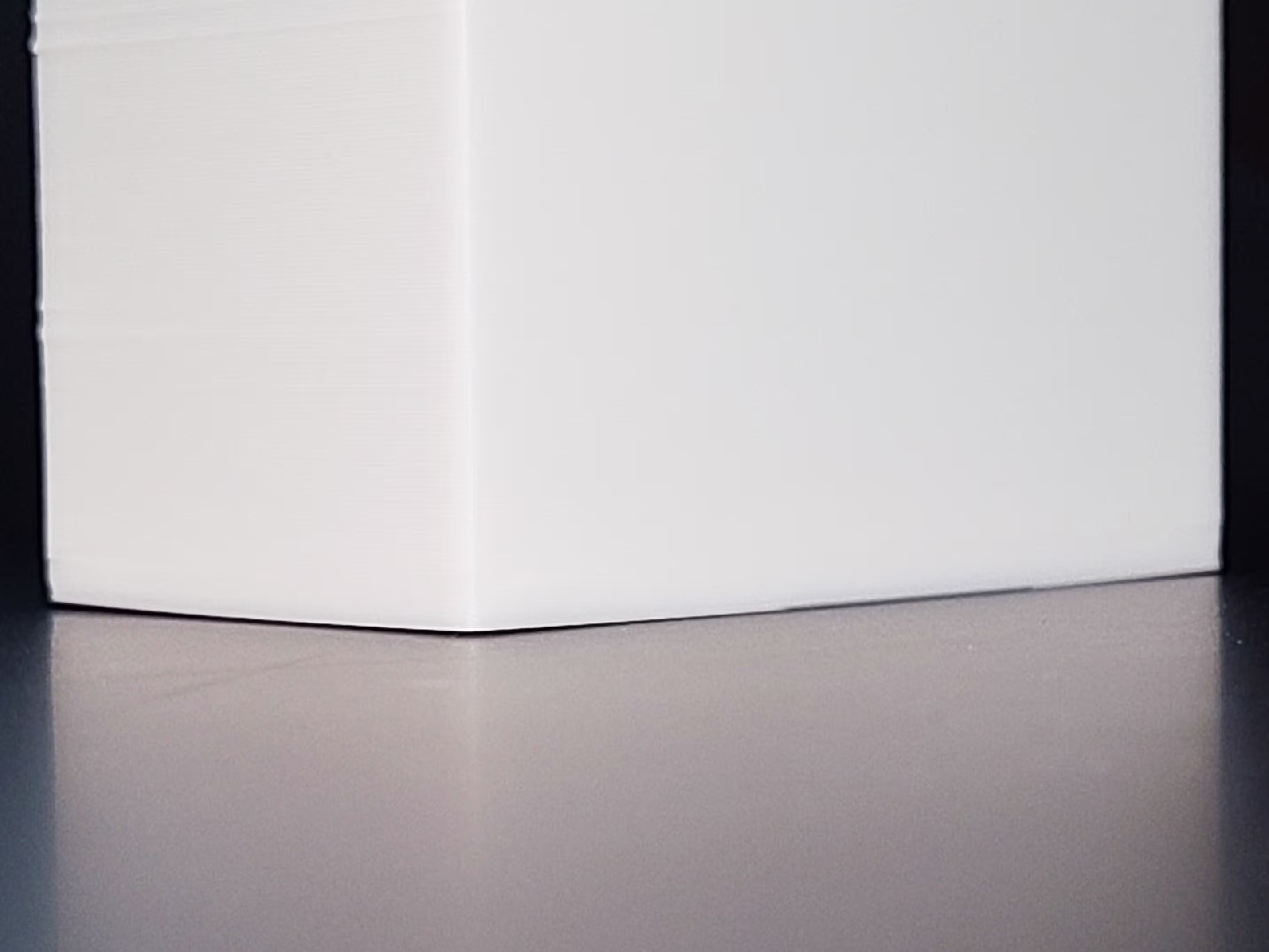
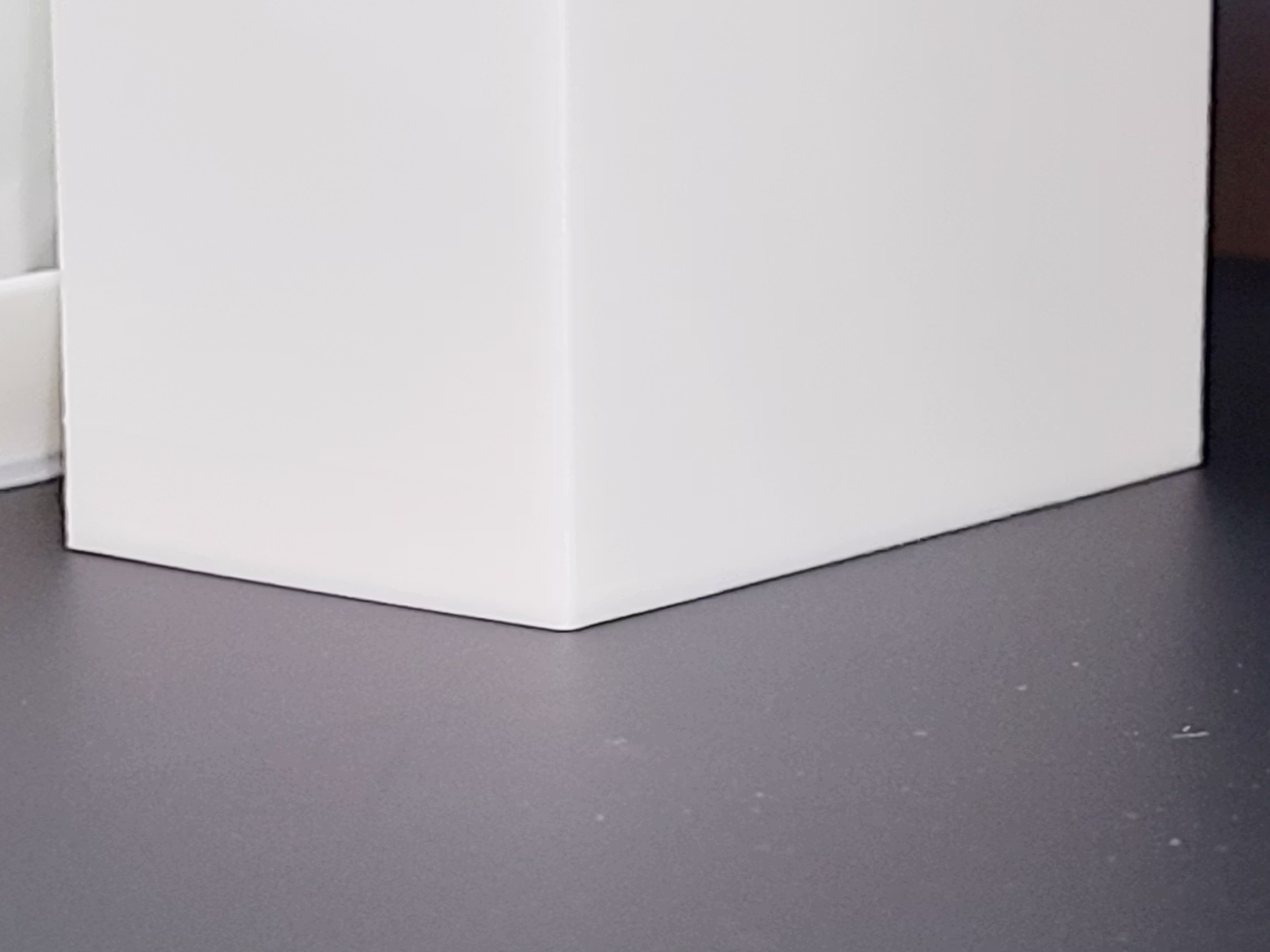
 WarpShield remains fully seated at the plate edge under 70% auxiliary fan, with no lifting at the shield’s contact edge.
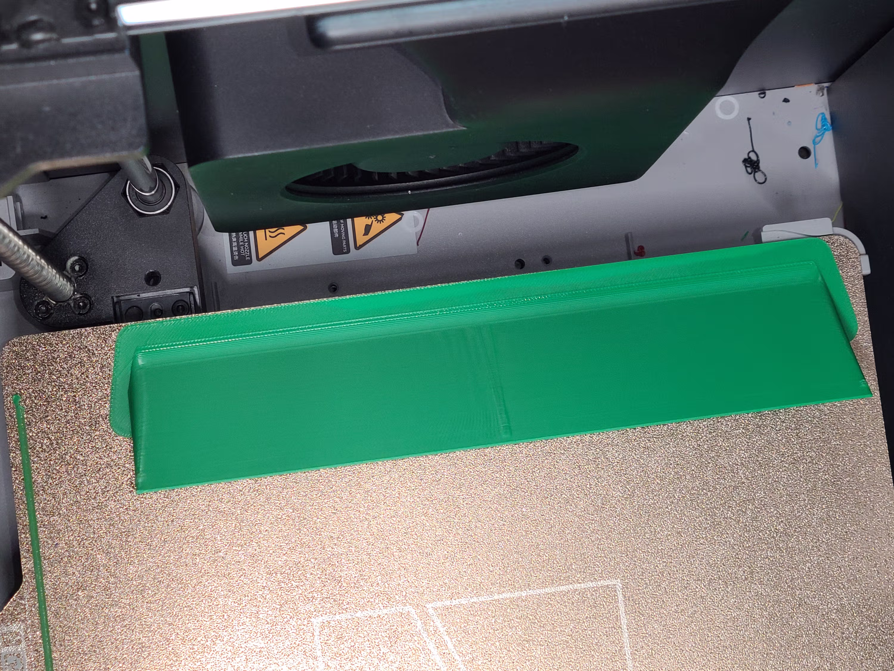 Brim lift is visible on the fan-facing side, but the lifting remains confined to the brim and does not propagate into the WarpShield body.